FWIW, being hit by ricochets is absolutely a thing!
(Speaking of which, maybe I should mount my plates higher up to deal with that a bit …)
FWIW, being hit by ricochets is absolutely a thing!
(Speaking of which, maybe I should mount my plates higher up to deal with that a bit …)
This project is great, and the aesthetics of Legavos are pretty awesome too!
I definitely plan to check out the code. My original twitch code has a few too many black box dependencies that make it trickier to work with. One day I hope make it more general, as I’ve wanted to build additional twitch-likes. Or maybe I’ll just be able to use your code 
@gertlex
Thanks, I’ve enjoyed trying to make it both look good and be practical/simple.
My gait cycle at the moment is very much WIP. I found a nice method for deriving continuous motion (ie moving straight, turning/moving at a constant speed), but it didn’t handle transitions well. So I re-wrote it iteratively, and then it had nice smooth motion even when changing direction, but would sometimes work itself into a joint configuration where there was no way for it to proceed in the desired direction.
So I’ve been letting it stew at the back of my mind while I work on the gun/turret. Hopefully when I approach the gait generator again I’ll have some fresh ideas.
And in other news, the initial system integration test has been completed. From the control software I can now walk, aim the turret and fire the gun:
One issue is visible in the video, and that is that the gait machine crashed at around 0:28 and was automatically restarted. It’s done that a few times now, so I’ll need to add some more logging/telemetry to it and find out why. It’s probably hitting a servo-range-of-motion assertion.
Yes, I also need to reduce the CPU load while walking - I’m missing far to many of my timing targets (the “missed loops” telemetry value)
So, my goals now are:
Congrats on getting it nearly to the “minimum viable entry” stage!
Unfortunately I haven’t been able to work on the Mech much recently, and probably won’t be able to for the next few weeks.
I did some more weapon tests in preparation for a mock “qualifying round” and the results were not encouraging. There were three groupings of shots! One is where you want the bullet to go - straight forwards, level when it exits the barrel. Another grouping was down to the left, and the other grouping was up to the right.
The front of the plunger has an indent to “center” the BB and means that the BB doesn’t slide along the edge of the barrel (which would give it an unpredictable spin). My theory is that the indent may not be deep enough so that sometimes the BB is not centered on the plunger.
Even ignoring the multiple groupings, the angular dispersion is pretty bad - probably about 3 or 4 degrees. The gun couldn’t reliably hit a tin can at one meter range! My theory is that the plunger that pushes the BB’s is oscillating as it moves forwards. There is some slop between the plunger and the barrel that permits this. I could make it a tighter fit, but this would increase the friction.
Both of these are easy modifications, so when I get some more time™, I’ll give them a go. Probably building your own gun is not suggested, but meh, it’s a fun challenge.
During these tests I also discovered that the friction-fit hatch that stops the BB’s coming out is a bit loose. After a couple rounds it falls off and then each the impact from each shot results in BB’s flying out the top of my hopper.
Options to make it wobble less might include polishing/reaming out the plastic, and greasing it?
Or make those parts using telescoping metal parts.
Or use a linear bearing of some sort?
Way back in 2020, I did a few more tests and decided this particular mech was utterly non-competitive. However it was functional - it could walk (slowly), it could shoot (inaccurately and with a range of ~4m).
One of the issues I have is that I cannot buy an AEG for less than ~$200, which is a bit more than I’m willing to spend at the moment. This limits me to auto-lances or building something myself.
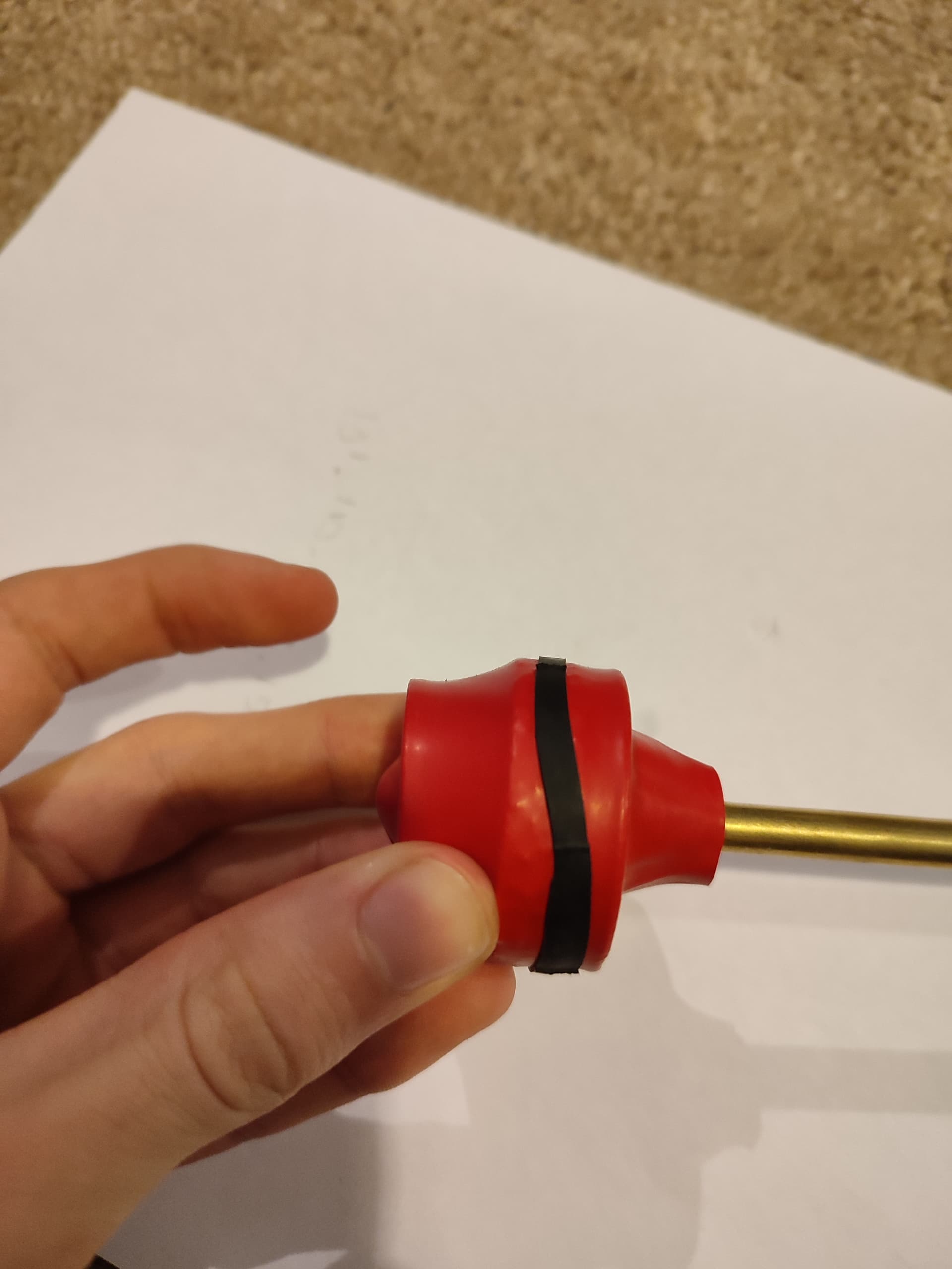
About a month back I came up with a good way to build an airsoft gun with only readily available parts.
The challenge is that any printed parts are inherently inaccurate, so lead to poor performance. The solution is to not use printed parts where required.
The latest iteration of test-gun uses a brass tube as the barrel and a balloon as the air chamber (after many trials I concluded you also can’t 3d print airtight enough systems).
It is much larger than the system on this mech, but I think that’s pretty much required.
So anyway, maybe I’ll have to dust this project off again.
That … is … amazing!
I thought about this some more over the past few weeks and realized I’ve been tackling the problem wrong. I’ve been thinking weapons first, but I should be thinking mech first. If I can build a platform with good mobility, I can stick an auto-lance on it, but a functioning air-soft system is not a mech. And, compared to the $600 for a set of servos (if I use cheap ones, I’d be looking at ~$1500 for AX-12’s by the time I pay import taxes), the cost of an AEG is reasonably minimal.
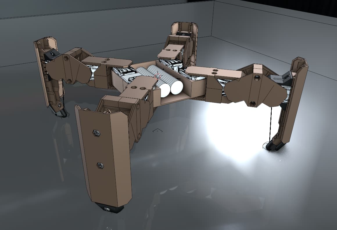
And so, Legavos II, walking research vehicle, is slowly being born. The aim here is to explore fully articulated legs using a set of XL-320 servos I already have. While they may not be powerful enough for a final mech, they will allow me to develop all the control systems, electronics etc. required for a bigger mech.
So here are some CAD’s:
In the position shown above, the foot tip is ~4cm away from the servo, but I plan to operate the legs “tucked under” to reduce that distance to 2cm. XL320’s have a stall torque of ~4kg.cm so the legs will stall out at ~1kg loading. For a sane factor of safety (heat etc.) that means each leg has to have ~200g of static load giving my mech a target body weight of 400g to enable a trot gait. I think this is doable.
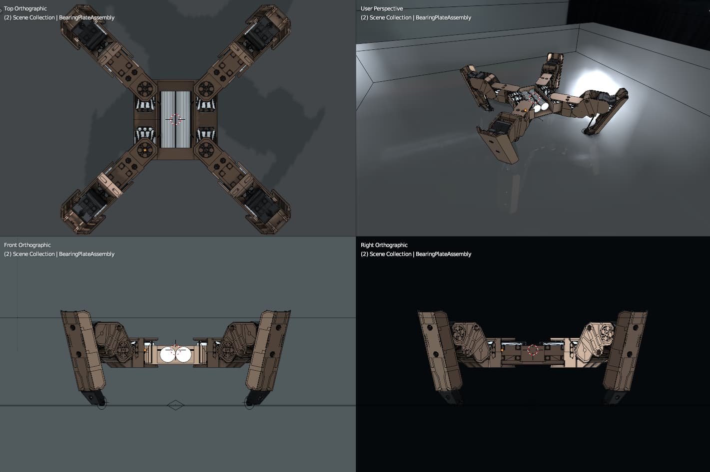
Here’s a shot of what is likely to be it’s more natural stance. In this pose (while static) all the load-bearing servos have a 2cm lever arm on them.
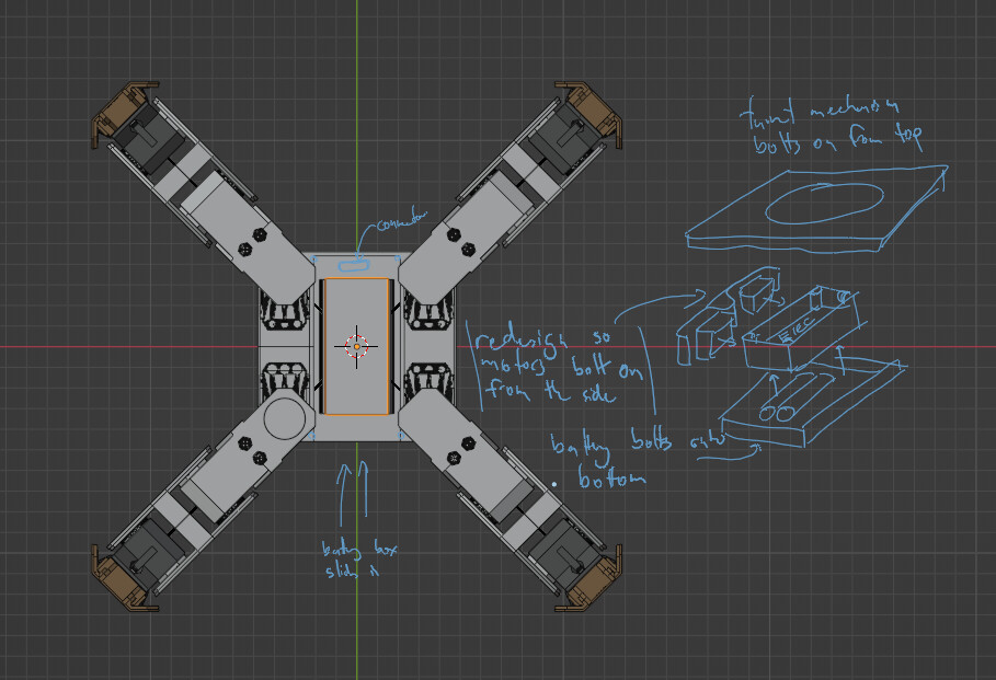
I love how in Blender I can just sketch ideas straight onto the screen so that I can pick up tomorrow where I left off today:
Design is heavily inspired by this diorama,
I’ve lobbed a few parts off my 3D printer, but somethings going funky with tolerances and overhangs, so I’ll need to sort that before I print too may more.
Any thoughts on those leg mechanics?
Yeah, that hip servo is the hardest working servo!
When building an AX-12 mech, I found that torsion springs helped a lot. If you can get approximately the amount of torque that “resting pose” would need, then all the servo has to do is apply the delta force, rather than hold the entire mech body weight.
Something like these:
This picture of Obsidian shows the springs wound around a spool that is mounted colinear with the axis of rotation:
(It’s the little round aluminum cylinders that look a bit like sewing thread spools.)
Hmm, that’s definitely given me something to think about. I did consider adding springs, but couldn’t figure out how to negate the whole spring-constant-thing making it harder to lift the legs. Torsion springs are a nice solution as they provide a (reasonably) constant force across the legs range of motion.
I wonder if I could even print-in-place some springs…
Just throwing some reinforcement learning around:

No idea if this will be useful or not.
I need to order a few more parts before I can start printing the actual robot. I also need to pick what microcontroller/embedded-pc I’m going to run.
Microcontroller: Almost nothing is in stock! There are some various Teensys though, and I like those, so that’d be my recommendation ![]()
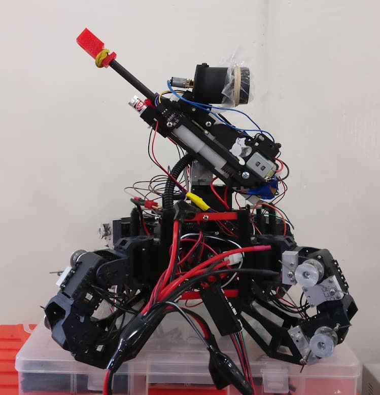
And … we have a set of legs!

No idea of the AUW at the moment, but I’d estimate ~700-800g. The servos have no issue holding it up (whew).
The main point of this chassis is as a software testbed. If I can achieve a stable walk cycle I will consider it a success and consider purchasing some stronger servos for V3. So At the moment I’m happy with off-board control software. If I were to onboard-it, I’d probably go for a SBC over a microcontroller just for convenience.
One thing I’ve already noticed is that there is a lot more code flying around just to describe the robot - more joints and their angle constraints, more important lengths/offsets.
One decision I have made is that this robot has exactly four bus’:
If I need to add custom devices (eg IMU, Lidar), I’ll do so by using a microcontroller to attach them to the dynamixel bus. If a device needs another voltage level (eg 3.3v) then it will “be on the device” rather than a bus that everything has access to. My aim is to keep the physical wiring really simple. The power/communications board has space for another 16 devices to connect (a total of 20 connectors - the legs are daisychained), which I think should be plenty.