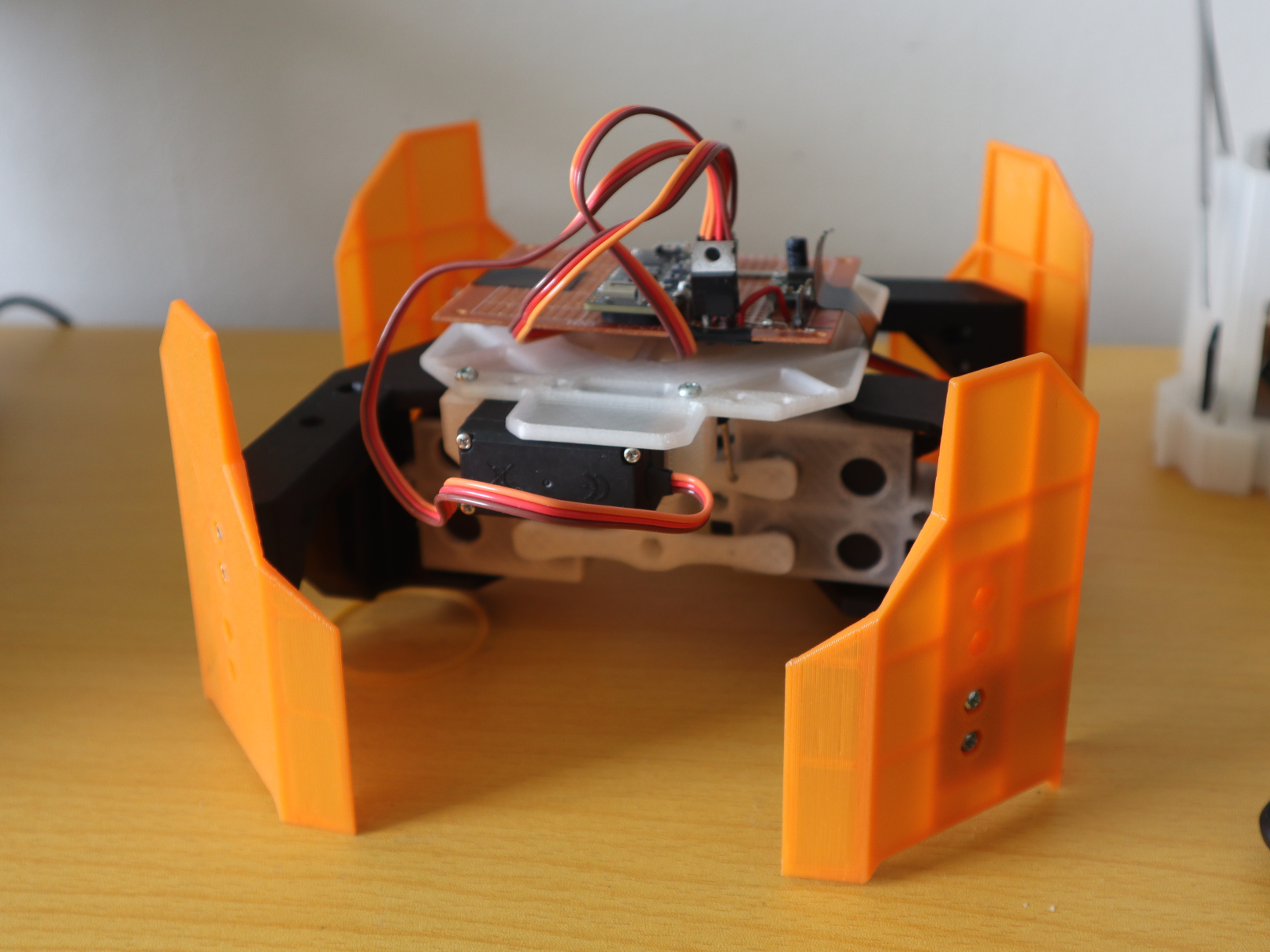
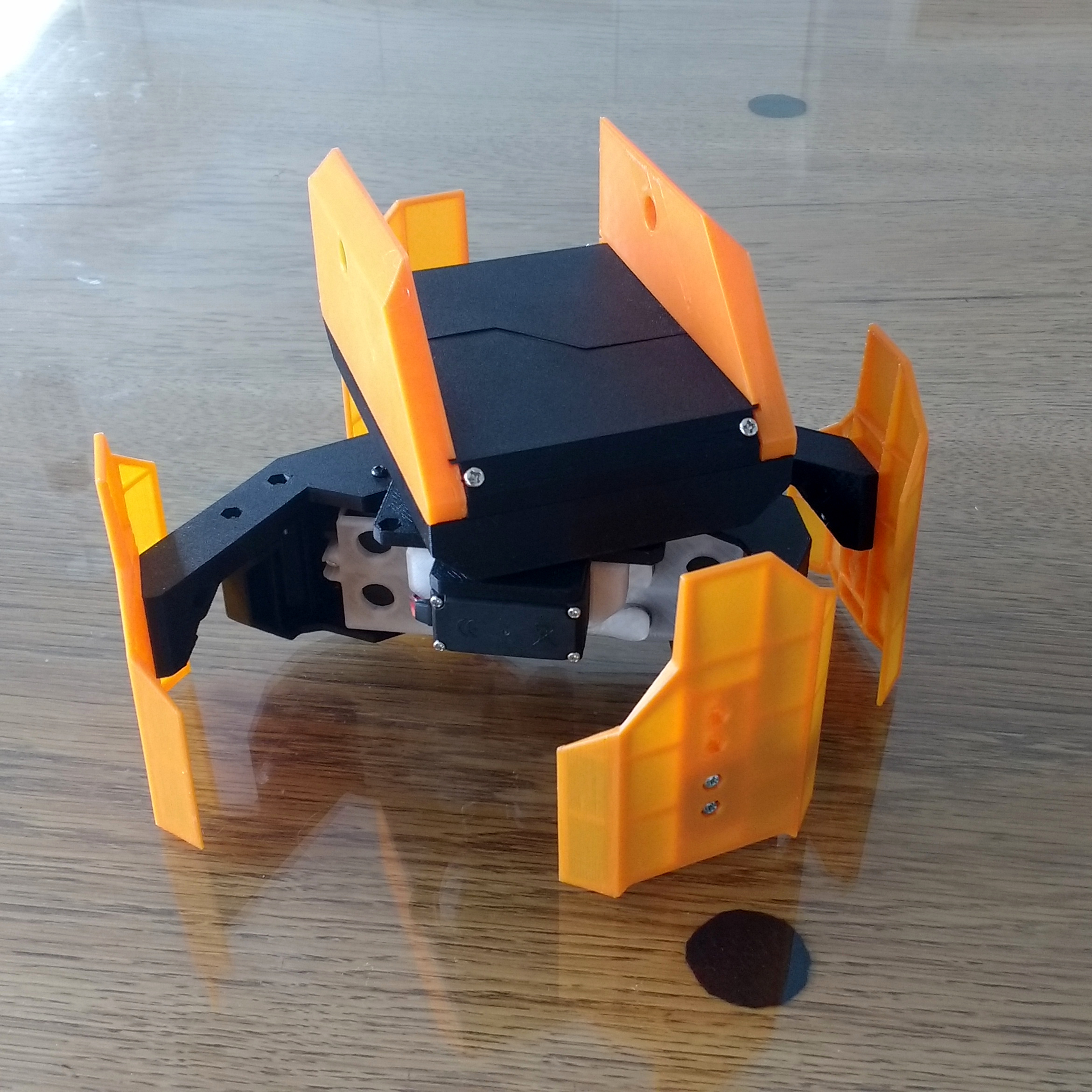
Legavos is my attempt to build the simplest mech-warfare robot that I can - both because the complexity of a build has proved to much for me in the past and because hopefully a super-simple bot will inspire some others locally to build their own as well.
The design is based on Gertlex’ Twitch, but adapted for quadrupedal form. (This is a statically stable quadruped, I didn’t see anything in the rules precluding static stability from quadrupedal mechs.)
This design requires only three servos for the chassis, which makes things simpler both mechanically and electrically. Control is done via the ESP32 chip, which has everything needed and it’s programmed in micropython - again something to make development easier.
Max Operating AUW: 1kg (at 1/4 servo stall torque)
Footprint: 20cm x 20cm
Theoretical max speed: 24cm/sec (not shown in video above. This is probably not achievable, but I’m hoping for >15cm/sec)
Step height: 2cm
With the current mechanics the payload could be doubled (to 2kg) at the cost of halving the speed, but I’m not sure the chassis is stiff enough for that. The chassis is mostly 3D printed, and needs just a handful of 5x11x4 bearings and m3x15 bolts to assemble.
Electrics
Servos: 3x standard MG996R servos
Brain: ESP32 running micropython. Internal loop rate of 50Hz
Battery: 2S lipo
This is a very cheap bot. The servo’s were bought for about $5 from china a couple years back. They are really horrid (±5 degrees backlash), but with this type of mechanics, it doesn’t matter so much.
Development plans:
Mech: Design turret slew system
Soft: Fix the internal event system so it doesn’t consume 30% of the CPU time looking for where to route events.
Soft: Fix walk cycle transitions (rapid changes in commanded velocities result in feet dragging or sudden jerks)
Elec: Mount up the camera/video system
Soft: Add support for camera feed to control software
Elec: Add in battery voltage monitoring
Mech: Armament.
Mech: Design gun tilt system
Mech: Possibly find a way to mount batteries on the bottom of the mech to lower CG
Soft: Switch from wifi-based networking to something else
Very nice! Glad to see you still working on your Mech.
There’s nothing against a statically stable Mech in the rules, either Biped or Quadruped. So you all good. The confusion over Twitch was whether it was a Biped or Quad. I think we would definitely categorize Legavos as Quad.
As your designing/testing don’t forget to consider the weight of the target plates if you ever plan to compete. At last years Maker Faire, Unlucky Cat walked fine until we put the target plates on it, at which point it had troubles.
The center of gravity is important on a statically stable mech - but not significantly more than on any sort of walking robot.
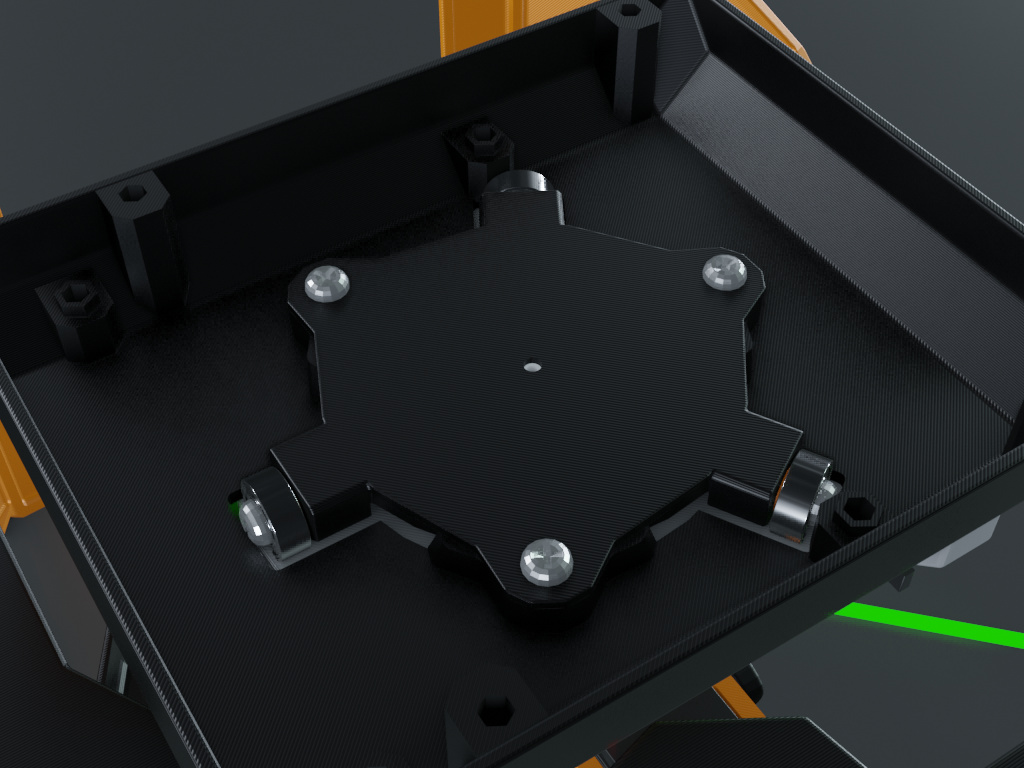
Here’s an animation I threw together:
The green lines indicate the edge of the stability region. The red circle indicates where the center of gravity must fall for the mech to remain balanced on the correct feet. The dot in the middle is on the centerline, and the ring is 15mm diameter. So if I balance the mech to have it’s CG right in the center and the CG is about 100mm above the ground, then the robot can walk on an 8 degree slope (ignoring dynamic events).
Thanks for clarifying the rules. I also wondered what class twitch fell into, and agree that this mech is definitely a quadruped.
For this type of mechanics I do wonder if it’s more a case of “styling” because a very similar system could be used to make something that looked rather like a biped. I think that it’s with the size of the participant pool at the moment it’s probably find doing it on a mech-by-mech basis.
Good advice on the target plate weight. I should probably make some dummy panels and and use them through all my testing. From my previous robot thread I gather that the weight of a set of light-mech target plates is about 120 grams.
The servo is mounted direct drive, and can’t deal with the low friction/high inertia of the turret. So I’ll probably modify it so I’m using it as a gearbox/potentiometer, and handle the control loop on the microcontroller.
Not top priority at the moment because it does work.
I tried to build a simulation in pybullet so I can develop the gait machine without needing to run the actual bot, but after putting in a bunch of effort to generate a URDF representation from my CAD I discovered that the URDF file format doesn’t support kinematic cycles - ie the parallel beam mechanism that is used to select which leg is raised.
So tomorrow I’ll probably build it “manually” in the pybullet framework rather than using the URDF importer.
I 3d printed some rather cylindrical airsoft rounds to try make a very simple AEG. I achieved ~25 FPS, which is about 7 times lower than the rules allow, and probably too low to trigger a target plate.
The target plates are actually fairly sensitive to impacts of the right kind. Ricochets from BBs pretty frequently trigger them, for example. Chances are, that weapon would trigger them.
It’s rubber band powered, but shoots 6mm bb-things.
I printed out a feeder tube, and was pleased to see it didn’t jam in the course of a 16 round clip:
This clip has half the rubber band tension, and it runs much closer to the motors maximum power point, although the projectile velocity is about half what it was in the previous video. When the world starts up again I think I’ll order a 30 RPM motor (currently it uses 100RPPM), which should allow for more powerful shots. Because this gun only weighs 24g and measures 2x3.5x[6-9] cm, there’s enough room for two even on a light class mech to bring it’s fire rate back to around one shot per second.
Or maybe I’ll switch to a 12kg.cm hobby servos such as the one I’ve got for my chassis. They tend to have the next size motor up. This would mean the bot doesn’t need two ammo feed systems.
Hmm, I just tried running at the previous rubber band tension, and the bullets didn’t have time to fall into the barrel, resulting in it jamming lots. It seems the distance from the pull-back point to the barrel-entry point is quite critical.
A package ordered from Aliexpress before CV has turned up at my door, and it contained some “500RPM” N20 motors. For whatever reason, these “500 RPM” motors have the same gearbox as the 100RPM version (and hence actually only do 100RPM) but have 1/3 the winding impedance and so can generate ~3 times more torque. It’s capable of drawing back the higher tensioned rubber bands with no issues at all. Looking at the pololu performance table, it looks like the old motors were the “LP” variant and the new motors are the “MP” variant.
So, uh, if you want to be sure of what you get, buy the motors from a proper supplier (eg Pololu).
And the rest of the turret mechanics is done. Now only the armament to design/mount
That said, the control system for the turret needs a lot of work. The pan servo is really struggling with the high-inertia, low-friction load, so I’ll probably re-wire the servo such that the microcontroller has more direct control.
The tilt is a bit jerky, but that’s because I don’t have any bearings to use on it, so that’s unlikely to have an easy fix. I see my local bearing suppliers does say he’s shipping things, so I guess I should place an order.
In the video above the battery is currently sitting where the gun will go. There is space for the battery inside the electronics housing, but I need to tidy up my wiring before it will fit
The robot’s at 700g now, a bit heavier than I was expecting but still fine. With 100g of battery there’s still 200g for the gun/ammo before I hit the servos operating limit. During test runs so far the leg-select servo hasn’t gotten above ambient temperature - but I haven’t yet given it an extended or high-speed test.
I ran the robot for around 10 mins with the speed turned up and all the servos stayed at ambient temperature, so the loading on them seems to be fine. Unfortunately the PLA of the leg beams is slowly sagging and the robot is tilting to the back due to the longer unsupported distance there. It’ll be fine if I store the robot on a stand, but I guess I should find some other material to make the leg beams out of that doesn’t deform over time.
In other news, I simulated a loading system. Rather than going for the “jam free” design I threw around in another thread, I prioritised the round/volume ratio of a traditional hopper. Even so, it’ll be really tight to fit 250 rounds into the turret.
I also ran some simulations with non-spherical (bevelled cylinder) rounds similar to the type I can currently print on my 3D printer. They required significantly more force from the motor, but (after some tweaking of the loader) they didn’t jam the system. It required a bunch more processing power and a higher physics simulation rate, so I only simulated short (1-2min) runs.
I’m not sure how much to trust the simulations - a simple simulation like this tends not to conserve energy (energy out > energy in), but if nothing else the simulations allowed some fast iteration over some dud designs and resolved some flaws in my approaches to this style of loader design.
However, the final test as to whether it works will only come when I print it…
Does your simulation include surface stiction, and static electricity? Both of those have bee implicated in “arcs” where the BBs build their own load bearing structure and refuse to fall down, before. Sufficient vibration will of course clear that
While it doesn’t simulate static electricity, it does have a friction model, and yes, I have seen it form arch’s over the place the BB’s should go. This was a significant problem with a screw-type loader I simulated, which required the BB’s to form into a 1D line. They would often bridge over the top, sometimes chains 5 or 6 long!
And because they’re an arch, they can be quite structurally stable.
I think that’s one of the reasons this style of loader works so well is that the BB’s only have to assemble themselves into a 2D “area” rather than a point or a line. That said, there are some hoop structures that can form as well… A key part to reducing this was to allow the BB’s to circulate around the motor. Introducing a baffle (or motor support) that stopped this circulation vastly increased the likelyhood of both jams and arches.
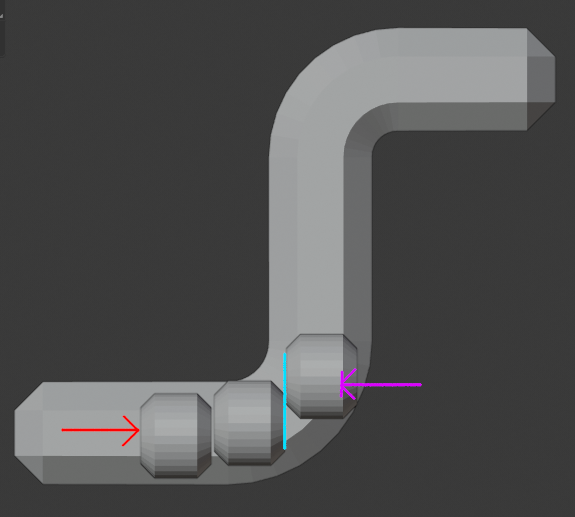
I printed out a loader and fed my bevelled-cylinder pellets into it. It runs for about 30 seconds before jamming. Two jam causes were discovered. One was an expected pinch at the place where pinches will happen - where it has to decide between going into the outlet pipe or recirculating. It was caught on the flat faces of the cylinder, so this should reduce in likelihood with spherical BB’s. The other was in the outlet pipe rather than the drive mechanism. As far as I can tell this is what happens:
If you get three (or more) of the cylinders all aligned in a row, then as they approach the corner, the cylinders may slide along their faces (cyan line) as they try to go up the tube. The non-cylindrical nature of both the pellets and the pipe (which is octagonal) results in the purple collision arrow. This is close enough to the point of contact between the pellets that the pellets don’t rotate. This jam is almost always cleared just by turning the motor off for half a second and then turning it back on. The rightmost pellet then pops vertically up the tube with quite a bit of velocity!
The solution: more gentle curve or router pellets.
I also fed a bunch of M3 nuts through the loader. To my surprise it did manage to spew a bunch of them out before jamming… My countries lockdown looks like it will relax somewhat in a week or two so hopefully I can get some proper BB’s then.
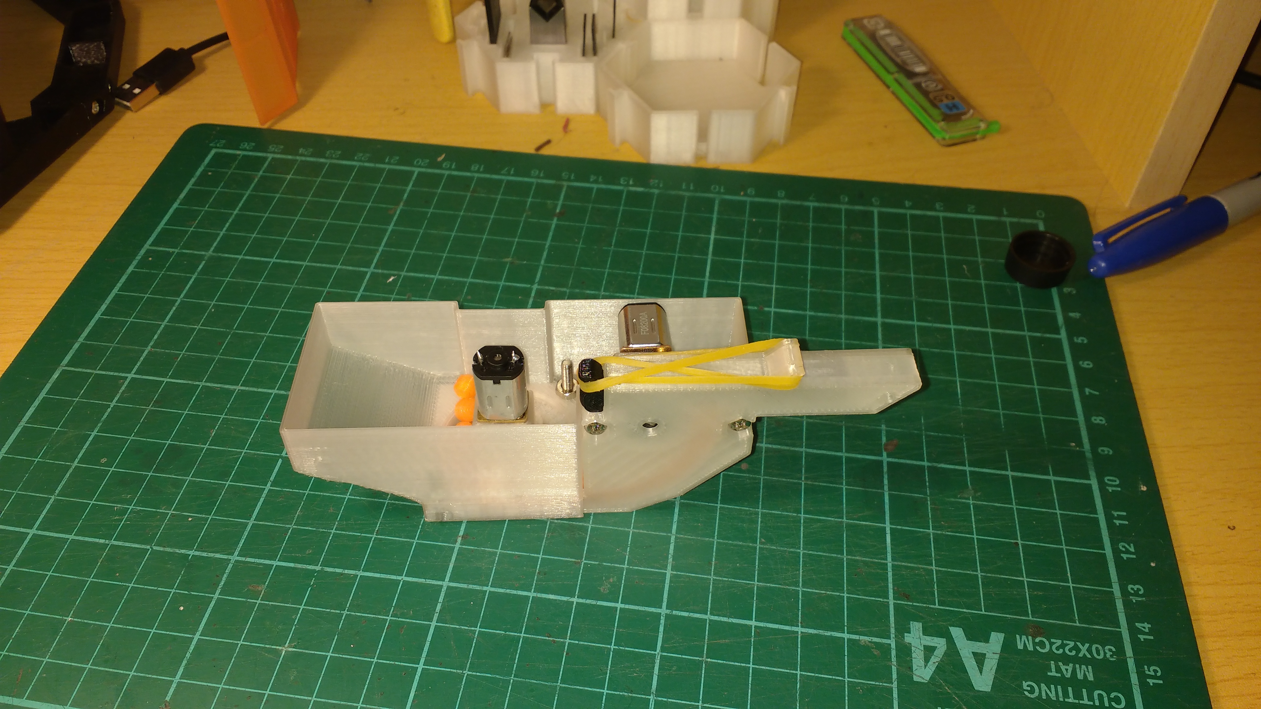
You can see the orange BB pellets feeding up from the loader to the breech. It’s a single big 28mm curve, so it shouldn’t have the problem observed previously with the cylindrical pellets.
Unfortunately there is a design flaw there: the loader pushed up the BB’s directly onto the teeth of the gun’s “plunger”, so if the loader motor is run at a even a moderate power, it jams up the gun-drawback-motor. Spherical BB’s will probably have less of a problem as well, as they’ll present a smoother surface to the teeth of the plunger. So I’m either going to have to do a redesign to alleviate this problem or perhaps throw in a reflective optocoupler looking into the breech so that the loader motor only operates when the breech is clear. (Turning a mechanical issue into a software one. Great).
I did a redesign where I rotated the gun’s motor by 90 degrees so that the BB’s are no longer pushing against the teeth of the guns “plunger”. It’s working quite reliably now. The gun itself does still sometimes “jam”, but the motor will continue to rotate and will draw the plunger back again. This often results in a double fire or dribbling a few BB’s out the barrel, but it’s better than jamming completely. I think that by tuning the distance between the plungers “withdrawn” position and the BB inlet, I should be able to reduce the likelihood of this happening.
I’ve also had a jam or two of the loader, but I think this will be greatly reduced with round BB’s rather than cylindrical ones. On that note, my local gun shop has opened up again (here airsoft falls under firearm regulations), so I have been able to purchase some BB’s.
I’m currently printing some parts to allow mounting the gun into the turret, and after that point I will hopefully have a slow, weak and underpowered - but hopefully somewhat functional mech.
The gun is now in the turret, but I had a problem with wires.
The largest consumers of enclosed space on my mech, in order:
BB ammo (Seriously, this is about 1/2 of my turret space and 1/4 of my total mech interior volume)
Batteries (a pair of 18650’s, yeah, I could use something smaller)
Servo wiring
Main Electrical board
When faced with wiring a bunch more cables into the turret I decided this wasn’t going to work. I elected to put a microcontroller inside the turret and talk to it over the dynamixel 2.0 protocol.
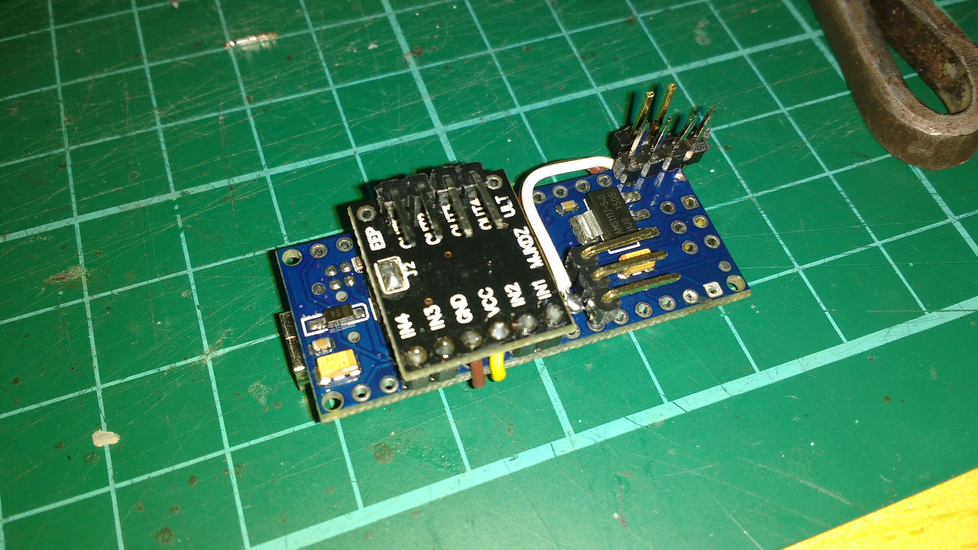
So here’s an Arduino Nano (it’s what I had that fitted into the turret) mated to a DRV8833 motor-controller with some headers for the external connections:
It will simulate two “virtual” devices on the dynamixel bus. This means that the tilt servo can be one device (easily replaced with an actual dynamixel servo if needed) and the gun can be another virtual device.
I’m pretty happy with the software on this controller so far, I learned how to use the Unity unit testing framework, and the protocol handling is fully abstracted from the hardware. There is still one more abstraction layer to thrown in (the control table) to make it easier to use, but the packet parsing and sending is now working nicely. I’m staying pure-C for the library so that I can compile it into micropython that runs on the main controller.
After I’ve finished the turret controller, and have got an actual walking-shooting-mech, I’m tempted to put another microcontroller in the “leggy” part of my chassis and thus have all the (dumb) servos “on” the dynamixel bus.
Well, a sack of BB’s arrived today, so I was finally able to fill up the ammo hopper and give the gun a proper test:
That clip is the last few rounds of ammo from a complete hopper (it holds around 300). They all fed through no problems so I now know the system is at least capable of operating for a full round (whew).
There were some software/hardware problems with the turret controller today:
The library I was using to control the servo needed the same timer peripheral as the gun’s loading motor. Fortunately there was another timer on board, but it’s only an 8 bit timer. So unfortunately my turret tilt system has an aiming resolution of about 2 degrees or so (I’m running the servo at 125Hz to increase the available resolution - yup, most RC servos can run at higher frequencies). The mechanical slop isn’t much less than that so it probably isn’t the biggest problem at the moment.
The Arduino nano has an onboard CH340 USB-UART converter. It’s connected to the Atmega328’s RX pin with a 1K resistor. Even when USB is disconnected, the CH430’s TX pin is driven high. This means that if you want any external source to drive the RX pin it has to have an impedance of less than 190 ohms, or be able to source more than 4.2ma in order to pull the RX line below 0.8V. I wasted most of today debugging this problem.
Tomorrow I’ll investigate using software serial, as this will:
Allow me to bypass the CH430’s overpowered pullup
Implement it as a half-duplex serial so I don’t need any external
electronics to interface with the dynamixel bus.
You can put a 2.2k to 10k resistor inline with the TX of the TTL converter. That will make pulling that pin low easier, and require less current. It will also reduce the risk that you’re overloading the TTL converter TX output pin! As long as you’re not communicating at megabits speed, a 10k resistor probably won’t get in the way of the serial communication.
2 degrees might be noticeable when trying to pinpoint shoot at distance. One option there is to use mechanical advantage to get more precision in the output movement than you have in the input motor, at the expense of getting less range of motion. Generally, you don’t need as much movement up/down as you get from a mechanism driven directly by a servo.
Finally, RC servos don’t generally need exact timing between each pulse these days. Thus, you can use the 8 bit timer to just shape the output pulse length (1000 to 2000 us) and then implement the pause between the pulses in the main loop. With 127 == 1000 us and 255 == 2000 us, and a 90 degree movement angle on the servo, you’d get 0.7 degrees resolution. (This of course also depends on how far your servo moves over the range – which I’ve found varies a bit between hobby servos.)
Good advise on the servo,. Yesterday I did something similar to what you suggest with “stretching” the off-time of the pulse: inside the timer overflow ISR I enable/disable PWM generation. A servo signal is always <25% duty cycle, so you can quadruple the available resolution. However, I found that my servo wasn’t really capable of motion more precise than 1 degree anyway,
There is already a 2:1 reduction on the output of the servo to the turret aim, but it also has about 1 degree of slop in it, so I think until I redo the system, 1-2 degrees of elevation control will be about how accurate it will be.
Of course, having accurate aiming is only useful if you have an accurate gun. In design, my gun is fairly similar to a shortened “Bullseye Sharpshooter” rubber band gun (from the 1940’s), which achieved about a 2 inch (5cm) grouping at 10 feet (3m). That’s an angular dispersion of about one degree.
I predict I’ll be luck to get 2 degrees anglar dispersion because my parts are printed rather than cast/bent/extruded.
In other words, if you’re more than 3m away, my guns dispersion will probably be larger than your target plates.
This is mostly hypothesis at the moment, and I should test aim repeatability sometime soon.