With Mech Warfare coming to Robogames 2023, and an initial scrimmage in December planned by R-team, it’s time I made some additional progress on this build!
Yesterday, I cleaned off the robot table, dusted off the box and took everything out, figured out where I was at, logged into Fusion 360 again, and a few other prep things.
Today, I set up a platformio project in vscode for the firmware for the new control board, and plugged in the feeder motor I had previously tested for the new gun (see previous thread,) and made sure everything worked as necessary. Also, I made sure I had a second Teensy 3.6 in backup, too – they’re out of stock at PJRC and won’t come back until 2023 because of The Global Supply Troubles.
I had almost forgotten; the box for Malum contains an RP-lidar device (it’s small and cute!) for sensing surroundings, but I’m pretty sure I won’t have time to integrate that and make that work. Chassis, basic electronics, Dynamixel servos, airsoft gun, 5 GHz video, s-bus remote control is all I need!
Dismounted the center frame from Malum I, so I can start moving parts over.
The center frame brackets are different, because I use a different video transmitter and different main circuit board. Plus a different gun magazine feeder, inspired by Don’s bottom-of-the-mech design (but I don’t have as much space there, so it’s still different.)
The legs are the same, so they get re-used, as do the main gun and front-facing camera, and the little brackets on the side.
I also read up on the SmartAudio protocol (again) for the AKK Inifinite VTX video transmitter I’m using; it allows me to set low-power “pit” mode as well as which band to use, from the microcontroller. This can be helpful come event day.
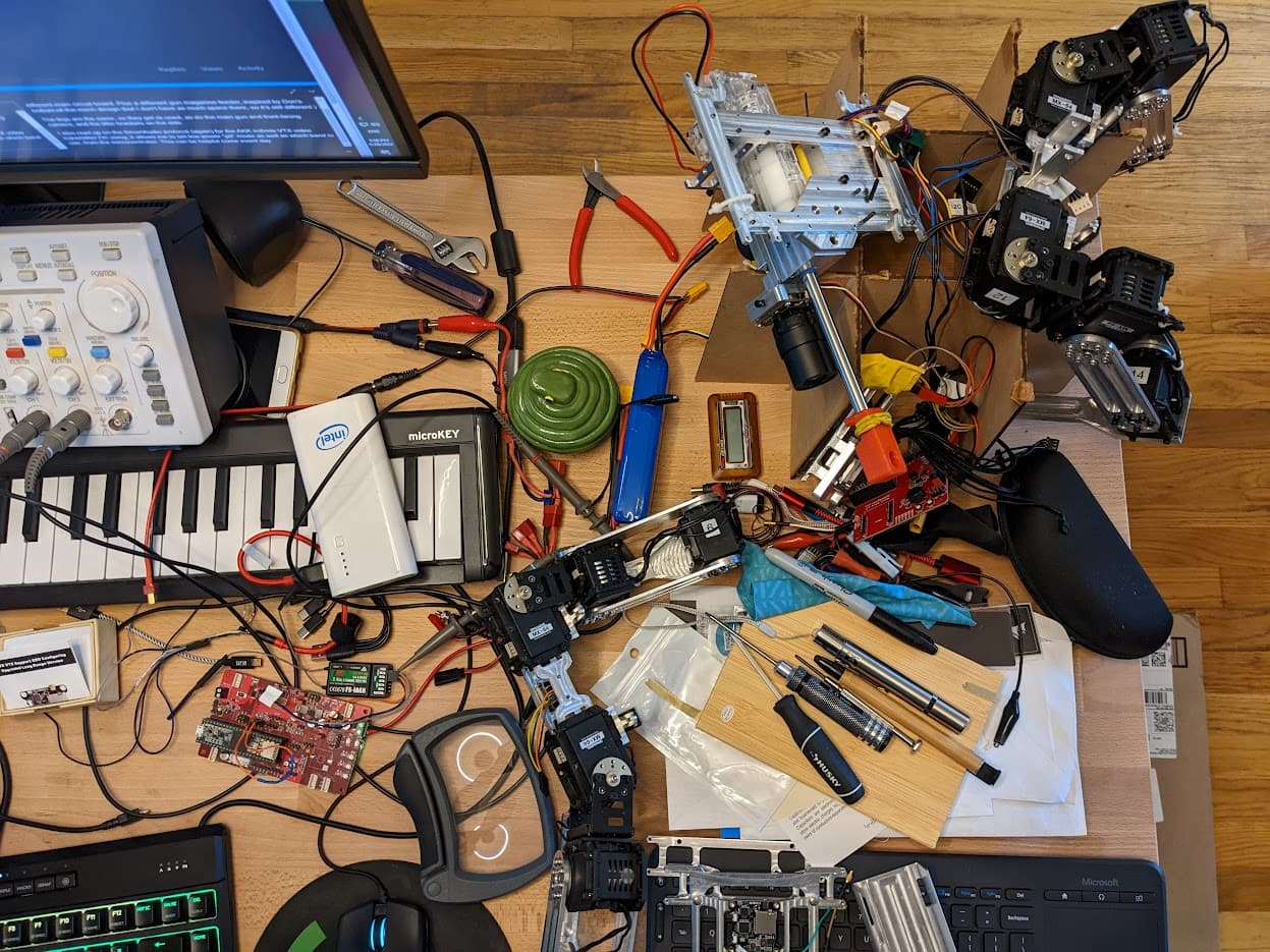
I also need to rearrange the desk a little bit to make proper space for the bits – currently it’s messy enough to be in danger of malfunction! (at least, wise from previous injury, I’ve taped the bottom of each circuit board with Kapton tape, to avoid placing them on metallic surfaces and shorting them out …)
I was not as far ahead on the new circuit board as I had recalled – it just had some test firmware to make sure each peripheral worked.
I tracked down the firmware for the previous iteration (Malum I, based on Teensy 3.2) and am starting to move one piece at a time over.
Today, I moved over the FlySky IBus decoder module, and made sure that the RX receiver was correctly bound to my transmitter, hooked up to the board, and sending data.
It controls just the gun PWM port, which currently only drives an oscilloscope, but one step at a time! At least those bits work.
Idle thought: The video transmitter I’m using (AKK Inifinite DVR) has a DVR, which means it must have an analog-to-digital converter for video. And it has overlay to the outgoing video for displaying which frequency/channel it’s using. To, there’s a chance that there’s at least a frame’s worth of latency between camera in and transmitter out in this transmitter – if so, let’s hope it’s not so bad it makes control harder. (Worst case, there might ALSO be delay in the receiving display – analog to digital tends to have those problems, and also tends to be the cheapest way to build things these days …)
I just confirmed I have two Teensy 3.6 still in original packaging if needed. Finally got the arbotix-pro out of my stash this week to a user in Spain where it will hopefully be useful.
@tician long time no see! That’s good to know. I checked the parts bin, and I have two of them as well, so I’m hoping that will be enough.
This week-end I had gotten a new CPU and motherboard for my birthday (yay!) but it turns out, even though the case physically fit the motherboard, it didn’t have the right stand-offs at the bottom, so I had to go case hunting. Luckily, “Central Computers” around here has taken over where Fry’s bankrupted and Best Buy capitulated! And then it only took four hours to diagnose and debug what turned out to be a bad stick of RAM that the BIOS wouldn’t diagnose, but would cause instand reset after POST… Why do we do this to ourselves?
So, not very much robot work this week-end I got some debug code set up and the low-battery warning put in, so that’s something.
Still not a well functioning human, so have not done much with Ripley in years other than a few failed attempts to print a new chassis with a crap printer. The original unheated bed is not flat and PLA warps way too much on the large pieces I need. Have a new flat heated bed waiting in a box, but it is not made for this printer so can only really print esun TPU or small PLA parts reliably until I cut an adapter plate.
Also had to transition away from the ~2013 netbook this year as 8GB just was not enough with all the bloat. I had tried to upgrade to this model mini-PC almost a year ago, but it refused to even POST. After I returned all the parts I learned the 2x32GB RAM had been revised to a different chip just before I bought it and was no longer compatible (with exactly the same damn part number). A bit annoying to finally need a full monitor and keyboard after so many years with the netbook, but 4-core/8-thread PN51 is tiny enough and fast enough for my needs. With 64GB RAM, not even firefox should require me to get a new computer for another 8+ years.
Amazingly, laptops with 8 GB are still being sold. I think that should be a crime …
Anyway, I’ve struggled to be human, too, although each of our struggles are different. (What a NorCal thing to say… But it’s true!) Glad you’re hanging in there.
Today, I got 3D prints of the target panel brackets. I had hoped to cut them out of aluminum, like the rest of the chassis, eventually, but started with a 3D print for fit, and, worst case, I can use them as is and spend time elsewhere.
I also disassembled more of the old build, to take out most of the parts I will be re-using. I could probably screw the new thing together now.
I’ve also been playing with the DAC of the Teensy 3.6, to play diagnostic sounds of various kinds, but adding even a modicum of smallish sound effects really drives up the programming time, so it’ll be a simple beep for now. Also, not sure I’ll have an amp and speaker on the bot itself – just using alligator clips to the pins for now, to have a convenient way of knowing what’s going on.
Things like clicking once per iteration through the main loop can tell a lot about how and when things behave differently. I think it’s a much undervalued diagnostic tool for many things!
I can’t have the USB UART connected when it’s actually moving around, and sometimes, the behavior I’m looking for only happens under load.
To be fair, though, that’s very much a non-essential luxury item, but it’s the shiny bit that caught my brain that day, and it has been helpful in the past. Sound is another sense, like touch, or smell. I’m sure we’ve all debugged at least one failure by smell in the past
Speaking of which – the tapping fluid I used for the leg stands when I made them, is an ester (not oil,) so it had gone rancid, and when I unscrewed them, the entire family complained that I was stinking up the kitchen … luckily, a soak in dish detergent bubbly water cleared that right up.
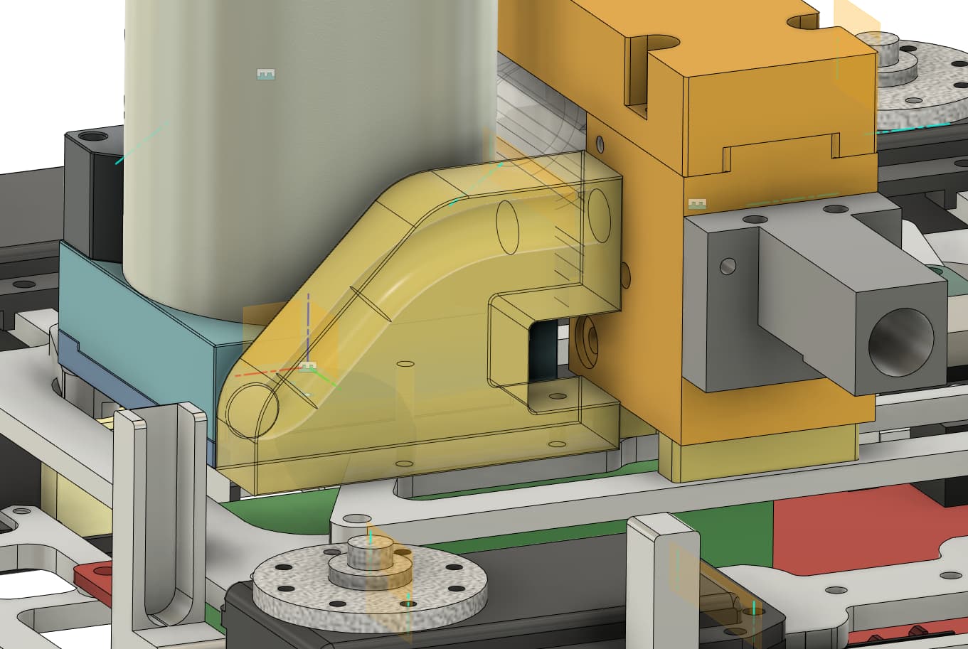
Today, I dry-fitted all the parts with lightly tightened screws (no thread locker yet.) It goes together very much like it did in CAD, so that’s a good sign!
I still need to get the channel or spring from the magazine to the chamber. There’s also a bunch of wiring still to do, and more software. But I’m starting to feel that this can happen in time! Maybe I’ll even get time to turn the 3D printed white parts into aluminum, too?
But I’d also like to make some covering/cladding out of something light, like styrene sheet.
My teensy carrier board has two buck voltage regulators (or, rather, one dual-channel regulator.)
I’m using the 5V output to drive a bunch of things (including the Teensy) and it works fine.
There’s a second channel, outputting 8.6V, to emulate a 2S battery, to use for the video transmitter. I’m using an AKK Inifnity SmartAudio transmitter.
Unfortunately, that half of the regulator seems to not be stable under load – it swings down to just a few volts when the VTX tries to turn on. Sadness!
Luckily, this transmitter actually allows up to 25V in, and I made each of the outputs of the regulator shunt through a header/jumper, so the actual users of the 8.6V output are all possible to isolate. So I just remove that jumper, and put a patch wire from the battery-in to the “9V” bus (which is now a “15V” bus) and problem averted!
It’s weird that this second regulator is so unstable, when the 5V regulator works fine, though (and I followed all the data sheet rules for layout, and have at least some practice building switching regulators in the past…)
But, you know what they say: A switching regulator is a negative-dampening oscillator, so … I guess I’m lucky I didn’t get a sine wave up to 2*VIN instead?
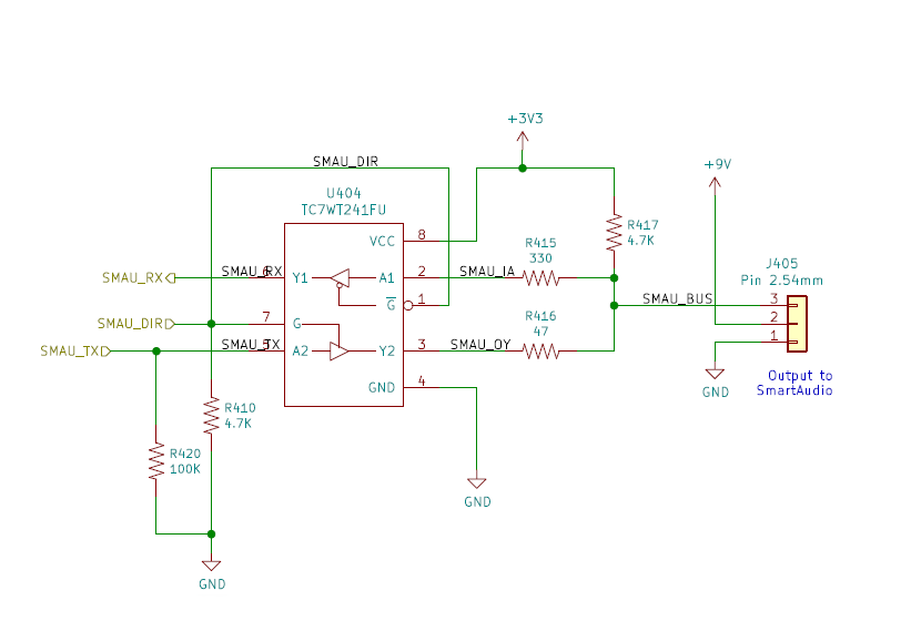
Here’s the SmartAudio circuit on my carrier board. I’m pretty sure this works fine – I’ve probed the enable pin with the oscilloscope, and it only goes high while transmitting a request, so it doesn’t attempt to drive the “audio” line otherwise (other than the weak 4.7 kOhm pull-up.)
Looks a lot like a capacitor is in the way on the line driver side of the VTX, which seems like a design bug.
Now, if they expected me to use a Schmidt trigger on the input, maybe this signal could be decoded, but that’s not what’s on my circuit board. And I’m not so sure I can take another spin of this board. Macrofab has stopped doing single boards (they’re only reasonable on cost once you get to dozens now,) and global supply and Chinese logistics are, uh, not in the best of shapes currently…
Now, I have to give props to Toshiba for that TC7WT241FU circuit; it’s actually specified for 4.5-5.5V VCC, and I’m running it at 3.3V, but it seems to be doing its job alright.
Maybe if I remove that R417 pull-up, the VTX capacitor might be able to keep the line low for long enough?
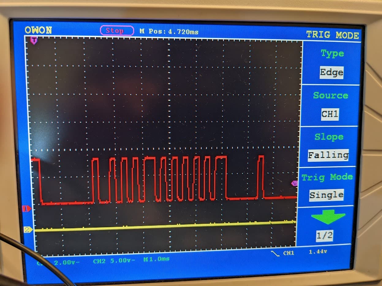
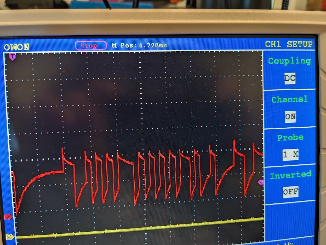
Is the DVR VTX spitting out a 3.3V or 5V signal? That second image looks a bit like there are a bunch of 0V and 5V pulses that then curve towards 3.3V via the pull-up resistor. …like maybe the output driver of the VTX is AC-coupled through a capacitor, which would make perfect sense if it is meant for outputting audio. Safest way to output audio from a PWM pin is to low-pass filter and AC-couple the signal out.
Thinking about it, many audio amplifiers ICs require AC-coupling the differential inputs as well, so any pull-up/down is likely to be outside of the design specs.
And 4.7k is not exactly ‘weak’. The built-in pull-up/down resistors in an ATSAMD21 are 20k~60k.
I mean, yes, 4.7k is firm enough to hold the line at 3.3V when nothing wants to drive it. But even a 100 Ohm weak-ass CMOS driver should pull it firmly towards 0.3V or 3.0V or better.
I agree – it looks like there’s a capacitor on the “smart audio” wire. The “audio” is the “microphone in” on the general wiring scheme of things – this is a video transmitter, after all. And the “smart” here is a method of using this available wire for a 4800 bps half-duplex serial protocol. But, as far as I can tell, this transmitter has the design flaw of putting the half-duplex driver on the “wrong” side of the de-coupling capacitor.
I found another VTX with SmartAudio support, for $15. (No built-in DVR, and the antenna looks dinky, but still …) https://amzn.to/3T78Hro
There’s also the Team Black Sheep folks. This one could also serve as the control receiver, except it seems all of the handsets/transmitters are out of stock everywhere: https://amzn.to/3EvD7iS
Also, a bit pricier. But the antenna situation seems sturdier, too.
Now, do I strictly NEED smartaudio? I’d want it for the “pit mode” support where the transmitter is turned to 0.01 mW, to avoid interfering others. I’d use the same switch for this configuration, as for the airsoft “arm” switch (my carrier board is set up for this.) But, I don’t HAVE to do that. I could use a DPST switch for “arm” versus “VTX” with only a little more wiring. But it’d be less elegant
I’ve been doing some reading/researching, starting with the idea of SmartAudio video transmitters.
It turns out, there exist devices that can do both remote control and video transmission all in one! And they can even go into/out of pit mode using the remote controller. (“pit mode” is where the transmitter power is lowered to 0.01 mW so it doesn’t interfere with other transmitters.)
But, those aren’t compatible with my current remote control.
Most of these controllers use standard radio modules/modems of various kinds, most of which are bidirectional. All the way back to nRF2401 type modules!
Unfortunately, most of them don’t allow bidirectional serial communication.
Also, in my experience, the XBees aren’t great in bidirectional mode, because they take several hundred milliseconds to switch direction when going back and forth, so low latency control with feedback isn’t possible. (You can of course use two XBees…)
But the “team black sheep” folks (“TBS”) build systems that actually expose a bidirectional serial link. (Actually, they expose either of the “MAVlink” protocol used by systems like ArduPilot for drones, or the CRSF protocol they built themselves.)
This protocol also sends the RC control signals over serial, which makes it much more robust to communicate with the 'bot than a PWM type receiver.
As you may recall, I have been using a FlySky FS-6S transmitter, which is intended for FPV drones, but gives me 10 channels of control data through a 115 kbps serial link out of the receiver, which is pretty great! It’s been quite reliable, too.
The closest I can get through the TBS people is something called a RadioMaster Zorro controller, adding a TBS Crossfire Nano transmitter, and then the Sixty9 Crossfire video transmitter and remote receiver combo for the bot.
This solution is kinda pricey, but it nicely solves the “how to configure video simply” and “how to control the robot robustly” and “how to receive telemetry back” problems all at once. Especially things like battery voltage and gun jam status would be nice to have sent back from the bot.
There’s also tantalizing hints about custom on-screen-display support built-into the video transmitter, but I haven’t been able to dig up enough information about that to believe it’s real, yet.
Now, there’s no real documentation for these protocols. At least SmartAudio had a nice PDF from TBS, but the CRSF protocol doesn’t seem to have the same. It is, however, supported in ArduPilot, BetaFlight, and similar open source projects, so I can start reading code to figure this all out.
There also seems to be two versions of the radio bits – “Crossfire” is a 900 MHz version, and “Tracer” is a 2.4 GHz version. The affordable FlySky controller I’m using is 2.4 GHz and has worked pretty robustly; I don’t know about the 900 MHz band. The 900 MHz XBee I’ve been using before has been higher quality than the 2.4 GHz ones, so it has that going for it. (The video is still 5.8 GHz for all the version.)
Also, the Radiomaster transmitter/controller seems to run open source firmware called EdgeTX (which seems to be a fork of another project called OpenTX – of course there’s a fork!) and can even be scripted using LUA scripts to show custom widgets on the built-in display.
Someone solving all these problems for me, and me not having to build them on my own, seems quite tantalizing, so I may be trying this out.
All because the SmartAudio on the AKK Inifnite had a capacitor in the way…
I started working up a simple feeder (thinking 3D printing for simplicity) which is one of the last remaining parts.
I recall seeing some bots (R-team?) use compression springs and funneling the pellets on the inside. That would be nice, too – I’ve got a packet of .24" ID 2" length springs coming from McMaster; I’m still thinking about how to clamp on to them in a way that doesn’t fall out if there’s a jam.
Meanwhile, a chonk of plastic will probably do it, as long as:
I get the inner diameter of the channel right
I get the registration with both outlet and inlet correct
It doesn’t bend or buckle under feeding pressure
Final thought: what’s the I.D. of a McDonald’s plastic straw?
Apparently, the screw hole in the CAD is further down than the screw hole on the actual part.
Presumably I re-modeled this at some point, but haven’t cut the new part.
I think I can still make this 3D printed plastic work, but I’ll need to carve it a little bit.
(Also, the flat-to-flat surface mating to get the holes to match up is not an amazingly robust design … but as long as tolerances are good and forces are low, it should suffice.)