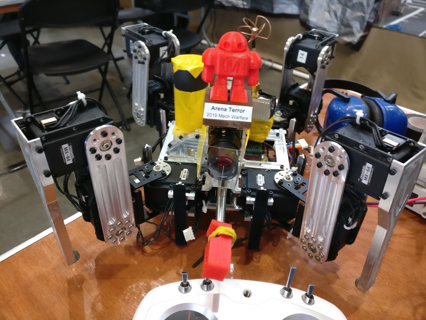
You may recall Malum from the 2019 BAMF Mech Warfare.
The main challenge with this bot was the gun system, which dry fired more than I would like. I’m going to fix this by updating the gun magazine to be a spiral-based feeder system.
When doing so, I will also pull together a number of functions that all lived on little separate boards in version 1, into an integrated “motherboard” if you will.
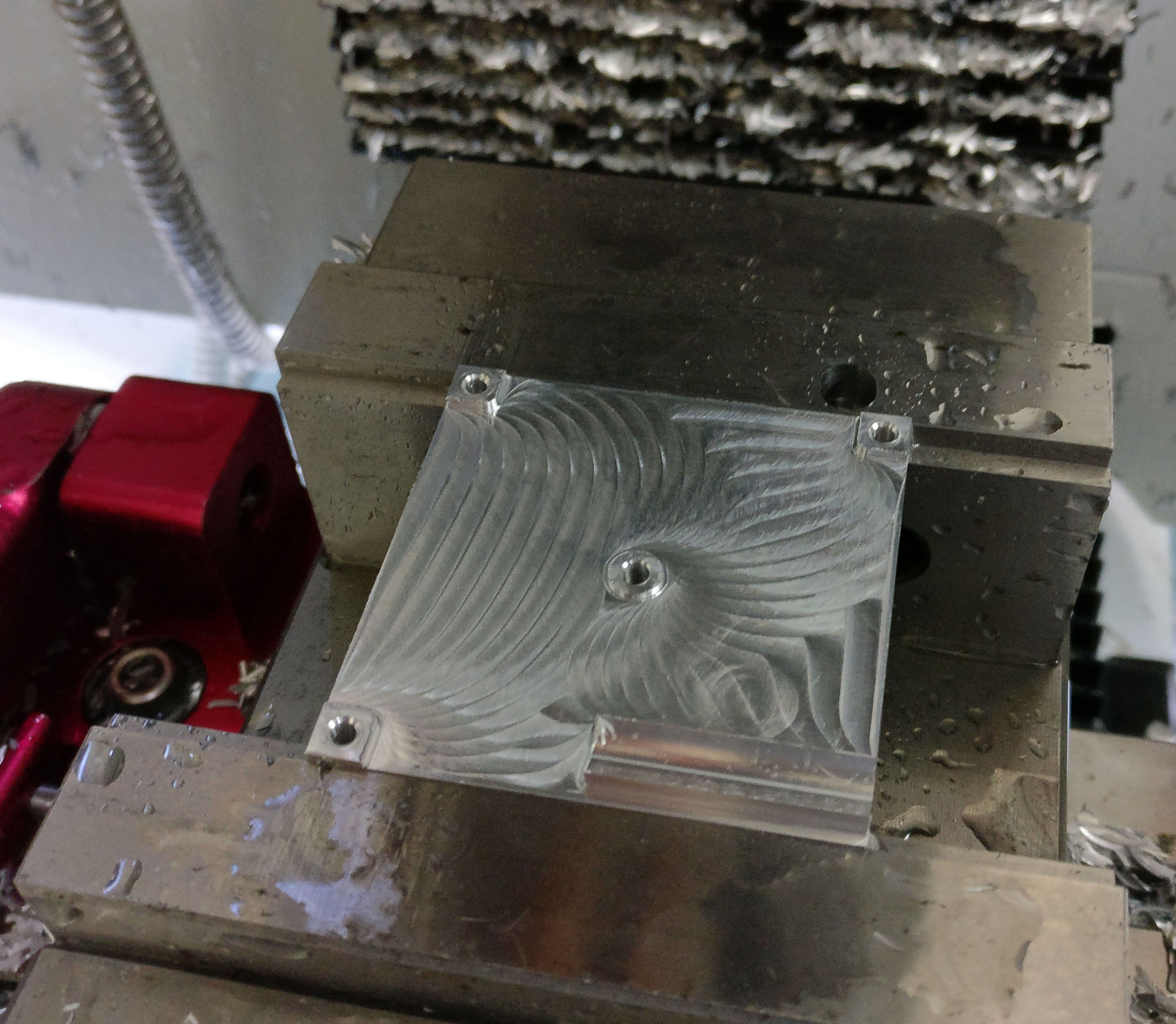
Here’s the next part of the magazine. You’re looking at the bottom side; it flips and presses onto the bottom plate from the previous part.
I tried making this composition in one part before, but there were parts I couldn’t really get to that way, so I ended up making it as two parts.
And agitator goes in the center to feed BBs through the grooved spiral on the edges.
That part’s next!
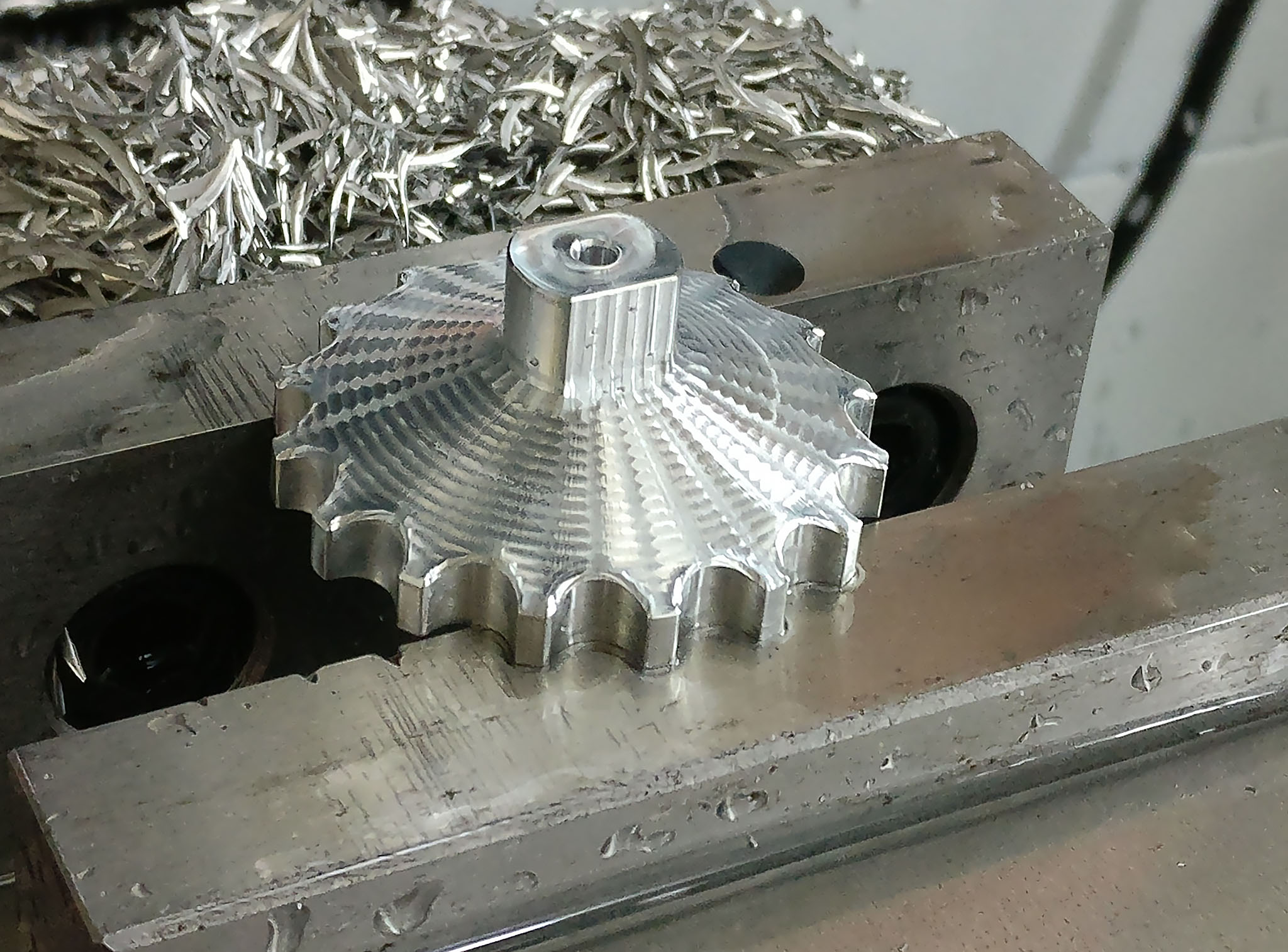
I made the agitator, and then pressed a ball bearing onto a 3mm pin and into the agitator housing. I think the fit was too strong, because the 3mm bearing got harder to turn – not quite bound up, but certainly under some stress.
Anyway, something must have gone wrong in my CAD or machining, because the BBs don’t quite have the space to follow the carved groove down into the chambers. Gotta give this more analysis.
The good news is that workholding and manufacturing approach I’m taking here works pretty well – no thrown parts or broken tools, and not even any re-dos this time around!
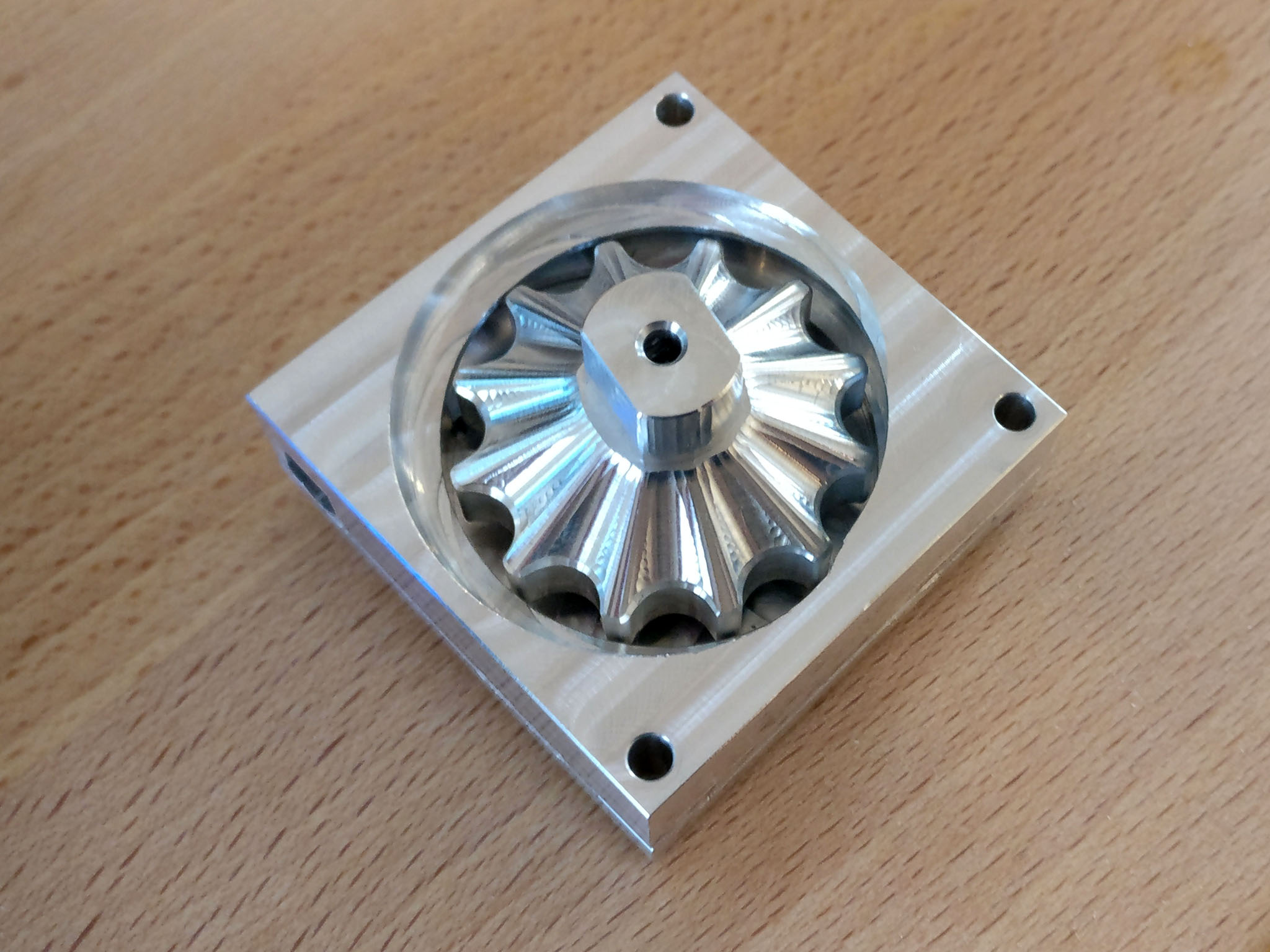
I figured out what went wrong – the thread depth parameter in fusion (used to mill the spiral groove in the center chamber) is thread diameter offset, and I entered the radius offset, so it’s only half as deep as it needs to be.
For pre-assembled/one-unit bearings, you always press-fit onto the shaft and slip-fit into the housing. If you press-fit both, it will deform both of the bearing races which will cause binding. If you have slip-fit on the shaft, then the shaft can spin at a different speed than the inner race which will cause marring/erosion of the shaft. If a bearing with slip-fit on the shaft seizes, the erosion of the shaft can be severe…
Yeah, I pressed both the shaft and the housing. Version 2 will slip the housing. Cad updates almost done, cutting/squaring stock tonight, making chips tomorrow!
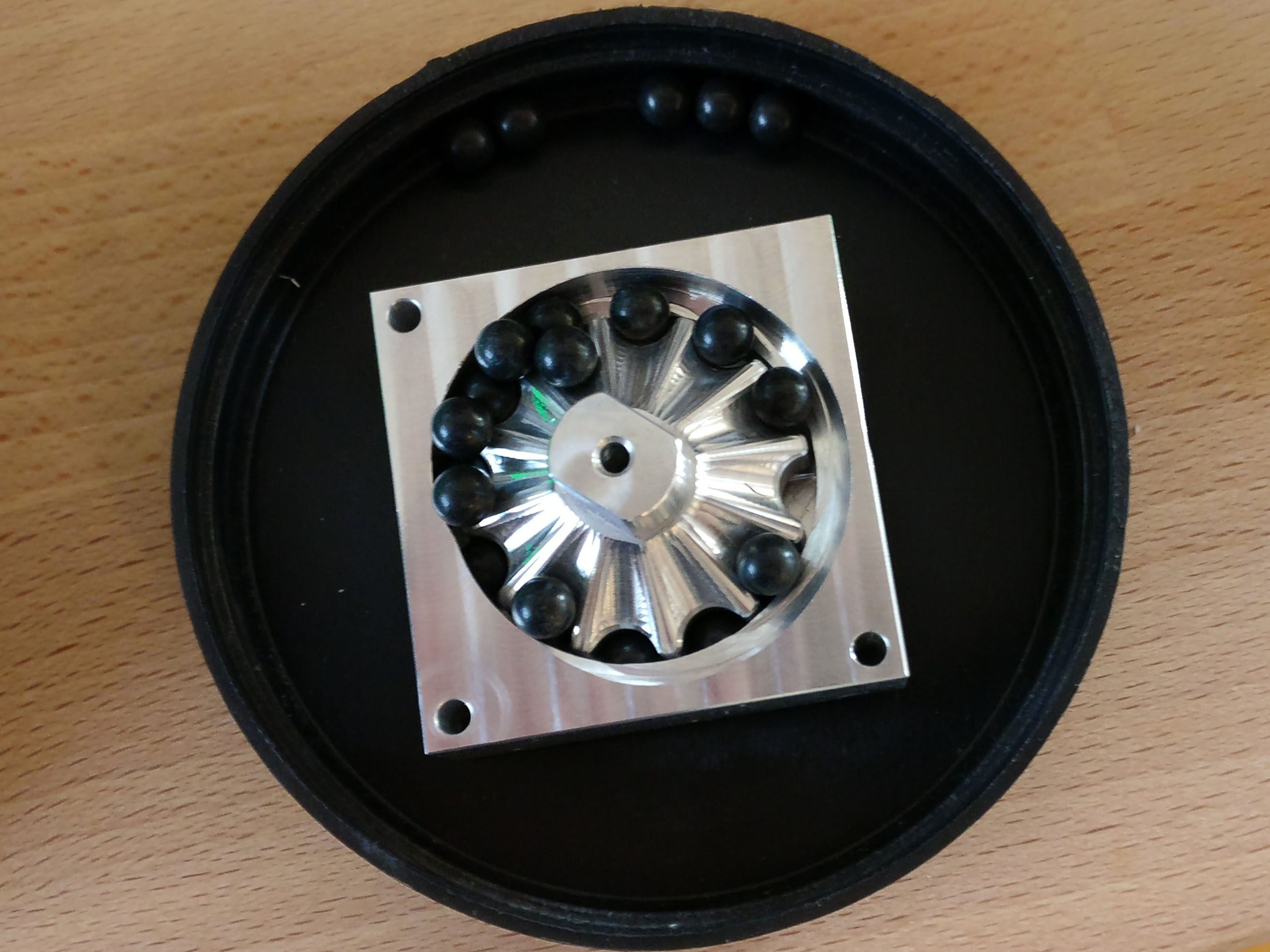
This iteration fixed the wrong thread diameter, and also loosened up the slip fits such that it seems to work alright. I also made it slightly smaller, and changed the finish on the top of the agitator.
So far, no BB jams when feeding, but I haven’t used it with a pile in a funnel on top yet. As we know, it’s impossible to 100% avoid all possible points of jam, unless you go soft/compliant, and even if you do that, the soft/compliant may end up “eating” the BB and cause a jam in the end.
I have the ability to run the motor fowards and backwards, and I have an encoder on the motor, so I can detect stalls.
Currently, I’m just feeding forward in unopposed mode (not yet mounted into the gun) so I’m not at the specific implementation yet.
FWIW, I used to try some motor driver from AKM to drive this, but even through several iterations of the board, that driver didn’t work (I think the footprint was just too squirrely.) Latest version, I plunked a DRV8870 on there, and it Just Worked (tm.)
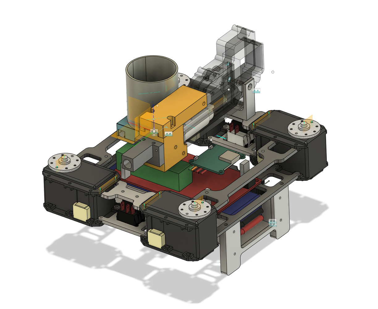
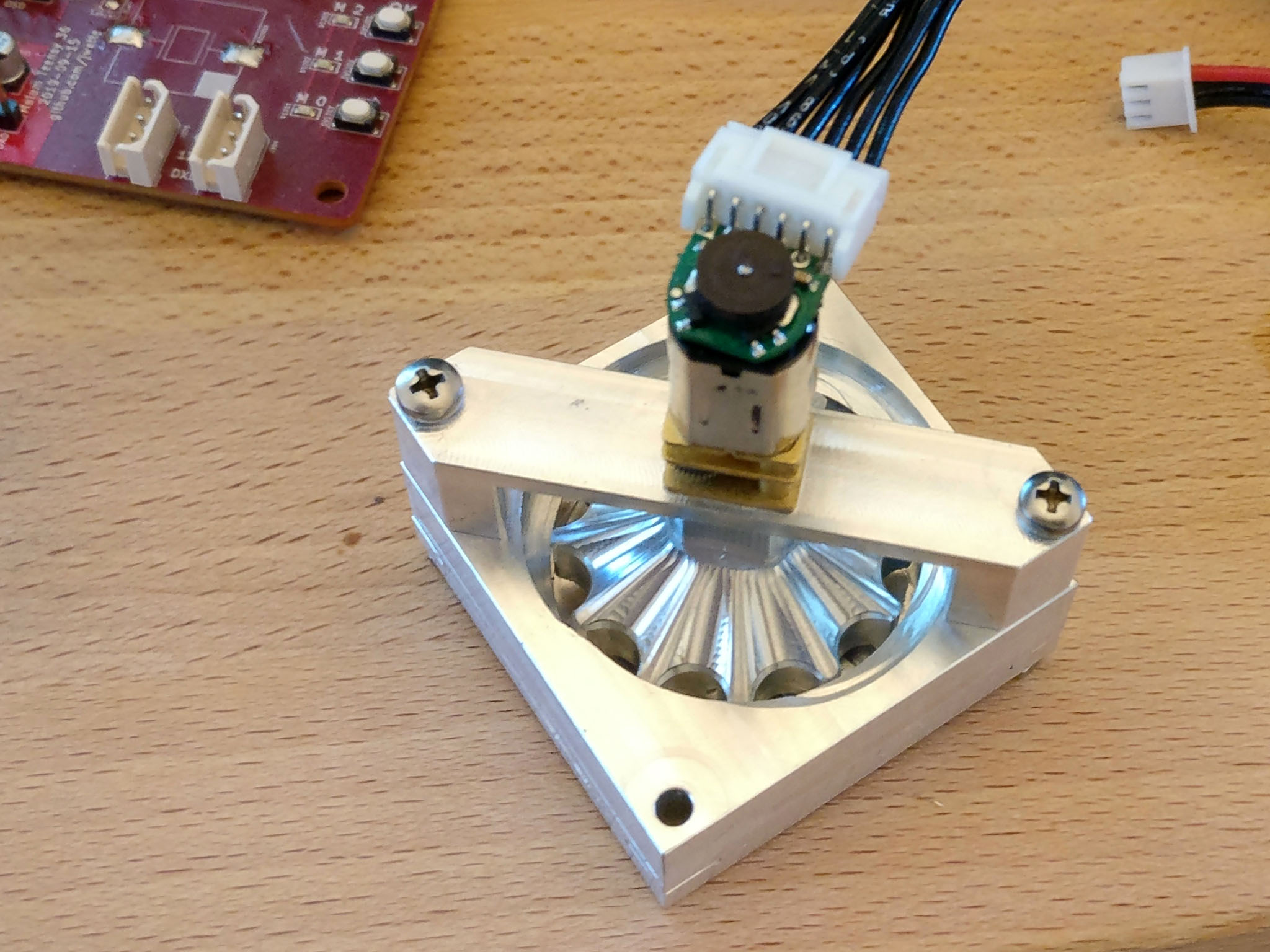
The motor bracket today. The parting line you can see is because I wasn’t super careful when probing the center when flipping the part (probing on unfinished sides, not taking the stock to finish first.)
You can also see the Pololu N20-style motor with their encoder solution on the back, which lets me read whether the motor turns or not. (And a JST PH wiring harness I put on it, to wire it to the control board)
The tube for the main hopper storage is on its way from onlinemetals.com, what with lockdown and all. My start-up can work almost entirely virtually, so I don’t have as much time on the mill as I’d like Gotta put bacon on the table. (Limited at Costco to one package per person.)
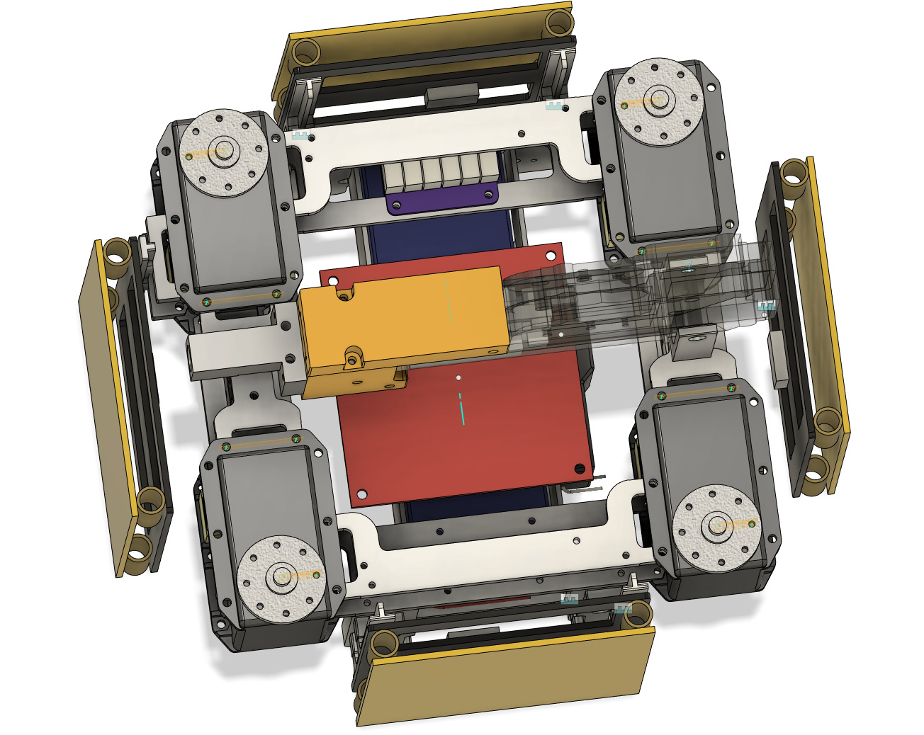
The scoring panels are about 100 mm wide (slightly less.)
As you can see, the hip spacing (“track” and “wheelbase” if you’re a car person) is pretty narrow. I can’t turn my legs much more than the quadrant 90 degrees. In the picture, “front” is to the left – you can see the AEG pointing that way.
Legs never stretch straight front/back, so the track (width) is probably OK but the amount of backwards movement for the front legs, and vice versa, will affect speed. If I turn the legs much more than 90 degrees out, I will hit the scoring panels.
On the other hand, a narrower bot makes it more maneuverable, and speed hasn’t been my limiting factor, so maybe I’ll keep it this way. Re-cutting a bunch of brackets would be a bunch of extra work.
On the third hand, I need to re-cut some brackets anyway for the new form factor for the controller board it integrates a bunch of functions that were separate little dangly Chinese boards in the previous version, so it’s necessarily bigger than the previous iteration.
I also need to re-cut the scoring board mounts, so I can put some wire guards across them to prevent self-scoring when strafing into toy cars and gas stations…
Engineering is all about trade-offs!
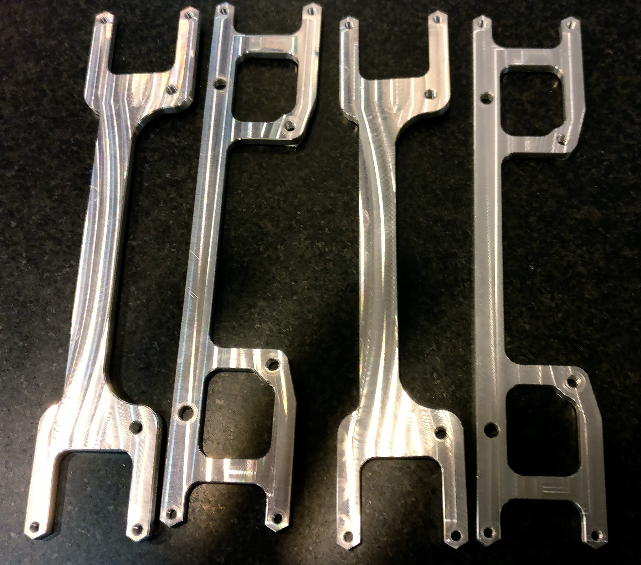
Now with the larger PCB, as well as longer “wheel base” to allow for further backwards rotation of the legs (not shown) without bumping into the scoring panels.
Also, to give space for mounting bumper guard wires.
I’m going to have to re-cut a fair bit of the brackets, but those are largely simple parts, so hopefully that won’t cause too much teeth gnashing.
And, yes, there are some cross brackets missing from the “top” to screw the video transmitter, magazine, and gun front into. That’s why I’m modeling this all out, to be able to make those brackets with all the right measurements …
The M2.5 threaded holes cut fine, but the thread mill I used for the M3 threads seems to not cut enough. I even increased diameter offset fro 0.5 to 0.6 (which is pretty sloppy in this context) and it’s too tight. I had to chase it with a hand tap afterwards.
I looked at the cutter under a loupe and it seemed alright, but for these things, you really need an optical comparator, which of course I don’t have one. (And, really, not about to track down one, pay for it, and schlep it to the garage … at least not yet
Is there going to be enough torsional rigidity in that chassis? As far as I can tell any bending moment across the chassis as a whole is going to be applied to just the plastic tabs across a very small area. (ie there isn’t any triangulation).
That said, I can’t quite see what’s underneath the chassis, perhaps the battery holder(?) will stiffen it.
By plastic tabs, do you meant the “ears” of the MX-64, where the M2.5 bolts go into the brackets?
Yes, that is a weakness. In practice, this robot did very well along that axis in 2019, so I’m not worried, though! (I worried about this when I first made this nut-less design.)
This is, as far as I can tell, a weakness of the MX-64 servos, because even with brackets that bolt onto the full flange, the weak point under torsion is the nut on the underside. In practice, I think there will be little torsion, though, because there is boxing between “upper” and “lower” layers. (There’s no diagonal bracing between the layers, though, so there is that. But the yield strength of the thinnest member is > 900 pounds, so not too worried about that.)
The XM/XH series seems to have made this better by using inserts and larger contact area.
Btw: everything made by me on this robot is cut out of 6061 aluminum, and bolted with 18-8 or black oxide M2.5 or M3 bolts. One of the main goals is to use zero nuts, and instead put threads in all the right holes, and apply thread locker as needed.
What caused trouble in 2019 was walking on concrete. The concrete + steel + metal frame was stiff enough that something broke in the gearbox of one of the servos, and its encoder sensor came loose, which in turn caused the robot to bend its leg inwards, which in turn caused the (expensive Maxxon!) motor to damage itself through overheating.
Solution: Only walk on the PVC foam flooring (Or add rubber balls instead of steel balls at the toes.)
In practice, I think there will be little torsion, though, because there is boxing between “upper” and “lower” layers.
Hmm. I was worried about it parallelogramming - both servos rotating in the same direction. However, thinking about it some more, I think you’re right in saying that there won’t be much torsional load - most of the time those members are either in compression or tension because the legs are sticking out on opposite sides, so create opposite angular loads.
But the yield strength of the thinnest member is > 900 pounds, so not too worried about that.
I think I’d be more concerned about the Young’s modulus than the yield strength. I wonder how much the chassis flexes when in a trot gait an taking alternate-diagonal loading?
One of the main goals is to use zero nuts
That is a great idea! They’re always so fiddly. On my mech, I’ve made sure all the places the nuts go are friction fit - so that when you undo the bolt the nut stays put.
What caused trouble in 2019 was walking on concrete. The concrete + steel + metal frame was stiff enough that something broke in the gearbox of one of the servos,
I had a similar problem with some herkulex servos when I used them a couple years back. The mechanics was a foam/rubber coated wheel that would encounter and slide 1kg steel cylinders. We thought that the foam/rubber would absorb enough of the impact, but after a couple hours of operation the “super engineering plastic” gears stripped out.
I do see that your servos have metal gears, so they should be a fair bit more robust, but make sure the amount of rubber is enough to actually cushion the impact.
Young’s modulus of 6061 is also pretty high Plug in 15 cm length, 18 mm-squared cross section, 6061 into a calculator, and I get less than four microns elongation for 40 N loading, which is the approximate loaded weight of the bot. And there’s at least four of these members in parallel across each side. This bot is more rigid than the previous robot (Onyx) that used dual 2mm acetal plates, and that robot was enough to place third in … 2017? Something like that.
Another goal of this bot is to be low on weight in the chassis. Some other bots (Immortal, Super Mega Micro Bot) load up on very good-looking casing, and then have to bear the load. That being said, I really like the look of the fully enclosed bots, so maybe I’ll figure out something really light to put on top when I’m done. Maybe some milled or vacuum formed styrofoam or something
Also, if I use styrofoam for cosmetics and it gets damaged by the airsofts, then SO MUCH THE BETTER!


 Gotta put bacon on the table. (Limited at Costco to one package per person.)