It seems it has been a while since the topic of the stand target panels has been discussed. Is this repository GitHub - bloftin/rbots: RTEAM Robotics Club repository still the best place to get details about the current target panels? I seem to remember the size as 3" by 3" but this states they are 3.5" by 3.5"… Can someone help me understand what the latest specs are?
My goal is to build a system that can use an Arduino Nano 33 IoT [ABX00027] instead of an XBEE for scoring system communications.
As far as I understand it, the target plates used at the 2019 BAMF are still the ones.
They are 3.5"x3.5".
For competition, the official plates supplied by R-Team will be used, to make for “fair standardization” but you can make your own stand-ins if you want to practice.
Integrating the wiring in the bot (running three 4-wire SPOX cables between the back and each panel location) is something I would highly recommend. Also, leave yourself a couple of inches of slack for connecting – I left some but not much, and getting enough articlation/force with my fingers to shove them into the socket was a PITA.
Thanks! It has been too long since I was able to compete with you guys. I’m hoping to build a wifi based scoring system so I can use it at West Point for practice with the cadets. I appreciate RTeam handling the scoring for us “competitors” but always good to have a set of your own.
I remember at one time talking about getting the panel data into the mech so a pilot could determine which direction the scoring hit was coming from. Any ideas if that was implemented?
I think the existing system uses the same mechanism as the old panels – a signal wire that’s low for 50 ms for panel 1, 100 ms for panel 2, 150 ms and 200 ms for panels 3 and 4. There was talk of maybe also making a 9600 bps softserial output (which really would be pretty simple to generate,) but I don’t think that’s implemented yet.
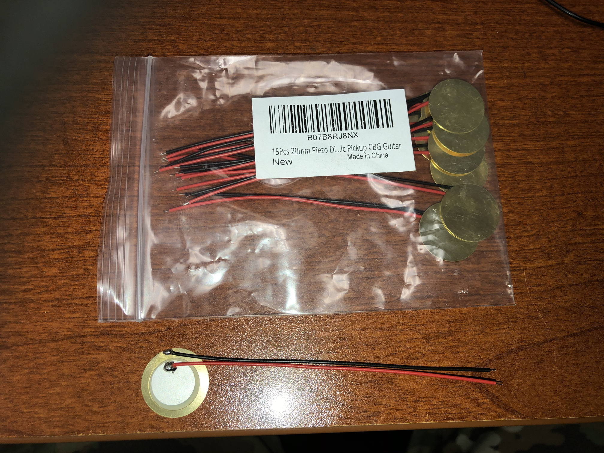
FWIW, I prototyped my own piezo panel detector, using acetal hit panel and a glued-on piezo buzzer as detector, and it worked fine! Get the right resistor for dissipating the hit power, and a zener to avoid over-triggering, and you can detect it as a pin change interrupt directly in a microcontroller, very little conditioning needed. If you want to make it fancy, use a trim pot and a comparator or opamp, to totally de-couple the MCU.
I just used something out of the parts bin They are all pretty much the same – a piece of crystal with wires and a bit of tin attached to them to transduce the noise, IIRC.
One main challenge is making sure you don’t blow your MCU when it gets a surprisingly-sharp shock – they can easily generate 30+ Volts when the conditions are right. A Zener/TVS and a resistor ladder is recommended.
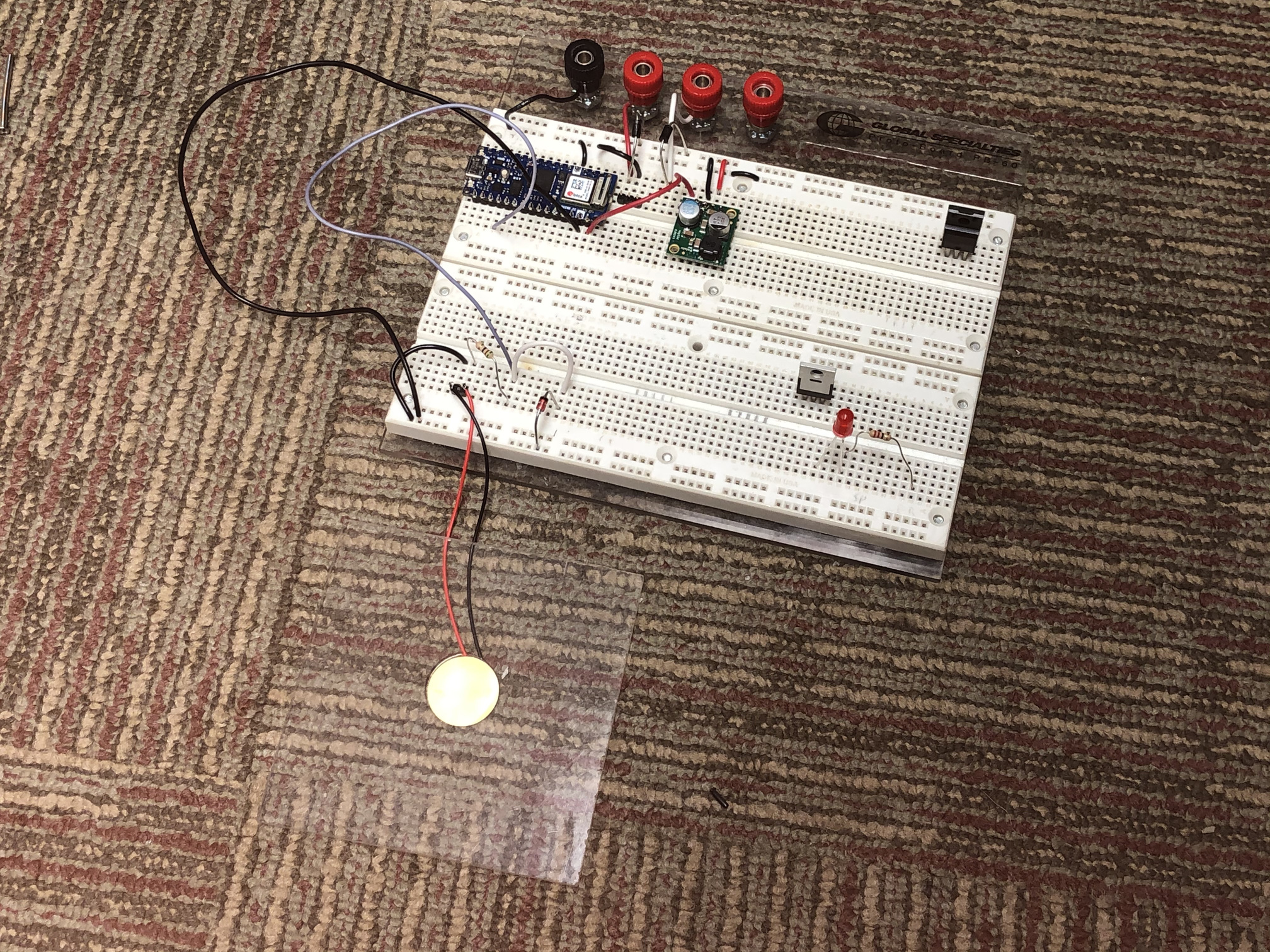
The sensors are working ok for my purposes but I’ve yet to start shooting at them with BBs. The intent is to use an Arduino Nano 33 IOT board and just measure the voltage levels at pins A0, A1, A2 and A3. The master plate will include the Arduino, a buck regulator and the simple circuit of the sensor, resistor, and 3.3v Zener Diode. Here is a picture of the breadboard trials.
Next step is to create the housing for the panel, the electronics, and the 2 cell LiPo battery that powers it. I’ll also provide a three pin connection that can provide a connection to the robot that “wears” the target panel. If you are wondering about communications, the Arduino will connect back to a computer over wifi that will process scoring.
I don’t think the AVR ADC will keep up sampling frequency fast enough to reliably detect those spikes, but I may be wrong! On the other hand, if you have pin change interrupts on those pins, and already have Zeners limiting the voltage, you can probably just detect the pin change with an interrupt handler.
Adjusting sensitivity might be harder, that way, though. Maybe use a potentiometer voltage divider to at least give you something to tweak.
Do you have an oscilloscope to look at the signals you’re getting?
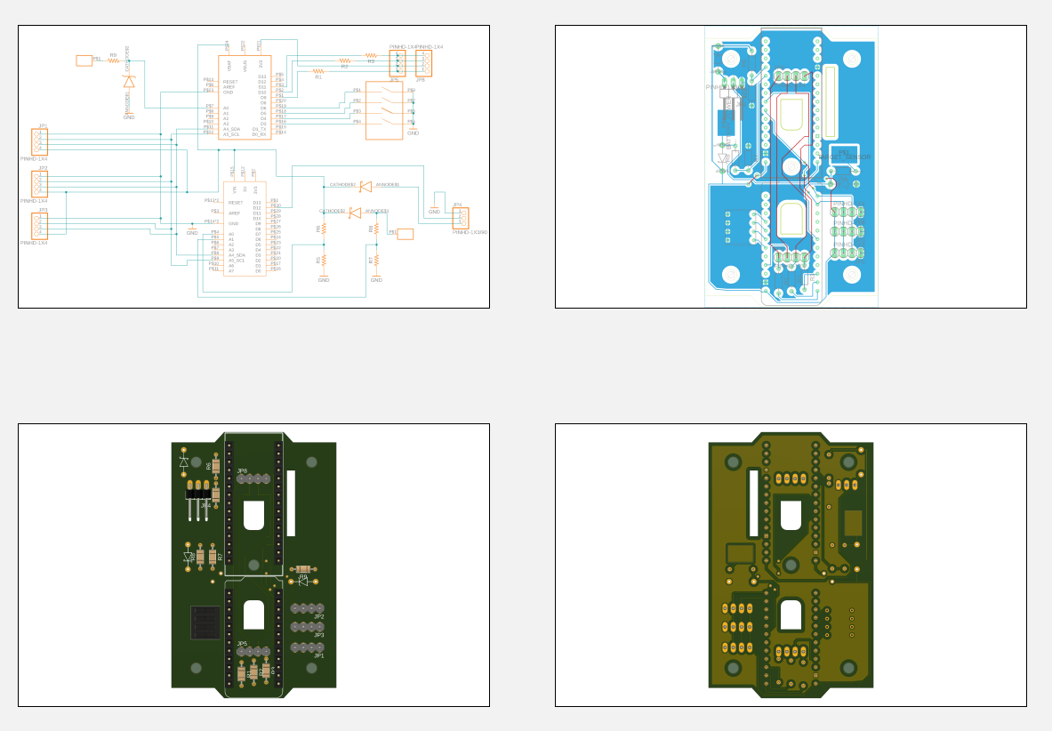
I was able to see with an oscilloscope, a nice signal spike created by the sensors. I’m still using zener diodes, as a precaution that I’m not creating the same signal that a bb would make. The zener’s will keep the ICs safe. As for the sampling rate, I ended up modifying the design. The master panel will have an Arduino Nano 33 IOT for communications back to the scoreboard computer, but for measuring the signal, I’m using the Adafruit Pro Trinket 3V3 to measure the individual sensor. I was able to come up with a nice routine that measures the and keeps a five signal average. It seems to be just as reliable as measuring it with the Arduino. As for the Arduino, it communicates with up to 16 Trinkets via I2C (I limited it to 16 with a 4 pin dip switch). In a sense, querying the remote trinket is no different than querying the local one. It made for much easier wiring as well. After some more testing, I’ll post some additional pictures.
I’ll try uploading the other file types shortly. As for the MCUs, I originally planned on using a single microcontroller to use its analog pins to read all four panels but having a handful of Adafruit Trinket Pros on hand, and given their blow cost, I decided to dedicate a single Trinket to each panel and it has the job of reading one analog input and turning on the paired leds. Only the master panel, the one you see here, contains two MCUs. The microcontroller driving the whole thing is an arduino nano IoT 33. It connects to each trinket via an i2c bus. I have yet to design a slave board with just the connection for the trinket, but that comes next. And also more testing. Eventually, the Nano will connect to the scoreboard PC over Wi-Fi and communicating via TCP or UDP.
 They are all pretty much the same – a piece of crystal with wires and a bit of tin attached to them to transduce the noise, IIRC.